That is exactly how they are meant to sit. Good to hear it went together easily, before i used grease, it took me a few goes to get the shaft in without the pins moving on me. The newer ones actually have a metal retainer to hold them in place, so grease was not needed
23 Feb 2013
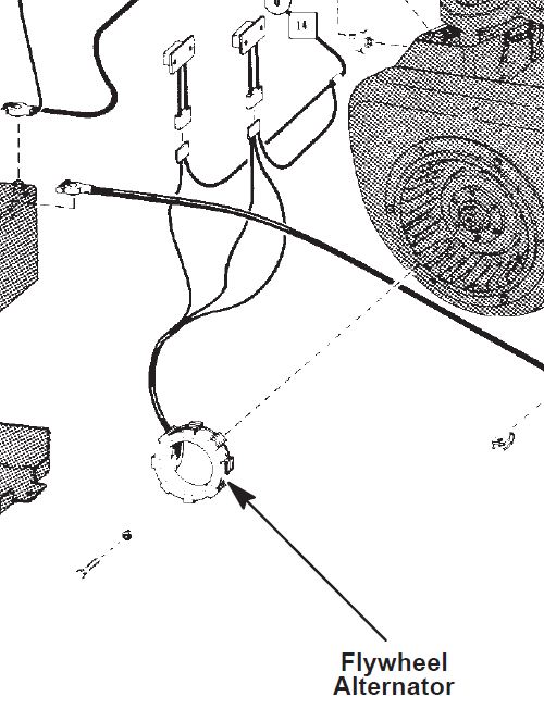
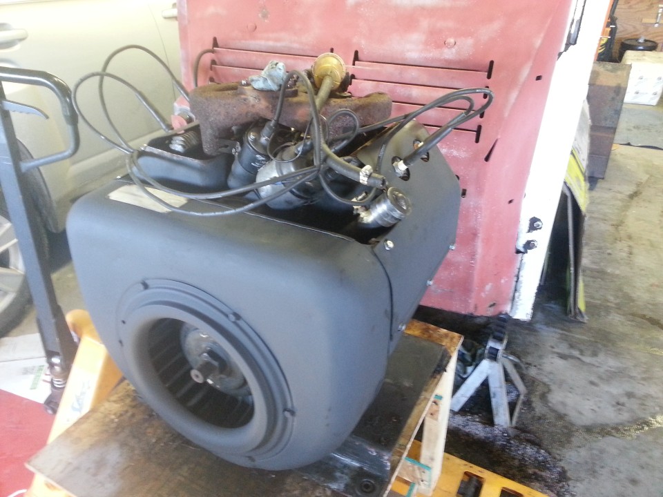
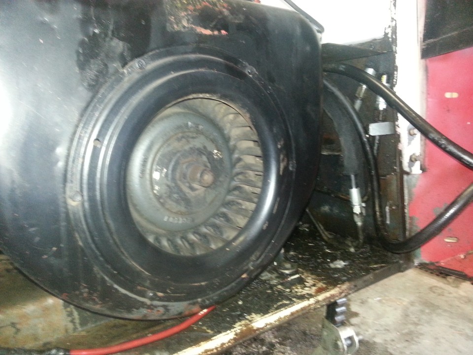
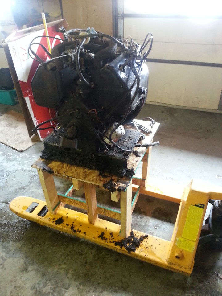
First Saturday off in I don't know how long. Decided the motor should come out. I had been waiting for this, as one of the things I intended to do was install a supplementary alternator on the universal side of the motor. More on this later. I had prepared myself, mentally, for the task. I was sure I was ready. A quick trip to work to fab the motor carrier, for which I'd been scrounging wood, and I was sure I would have this waxed before third coffee.
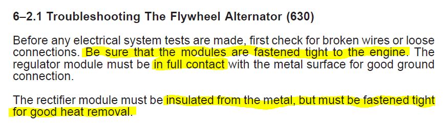
The beast in the bay:
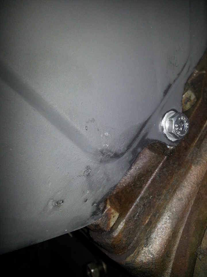
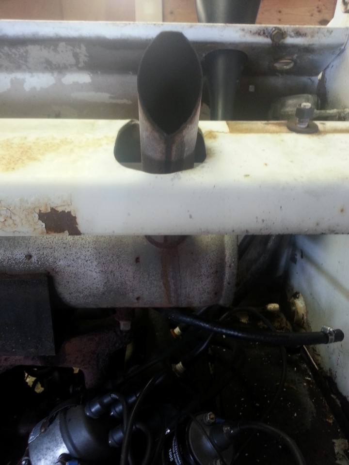
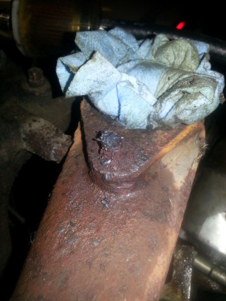
Before I loosened the bolts, I contemplated the job. Then I saw this:
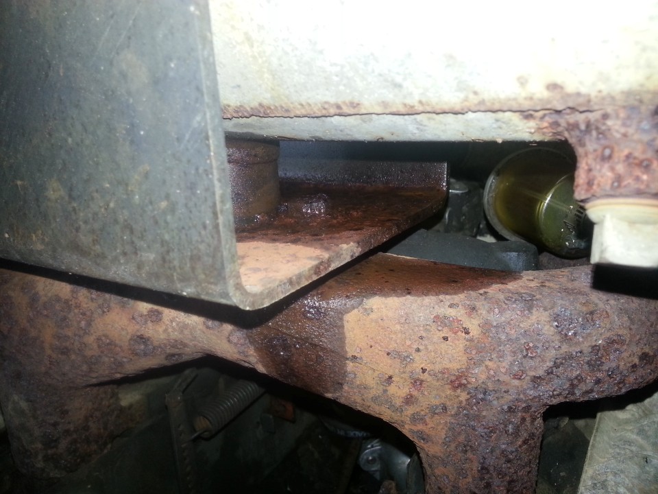
In a previous post I wrote about arrogance being the feeling just before monumental failure. I knew what awaited, and plenty of WD40, of praying, and effort did not loosen then bolts that I knew would be rusted into place - I have "opened" two wrenches getting these loose (a cheap 9/16's and an expensive 14mm):
Despite all sorts of non-destructive removal techniques, the bolts would not budge and eventually the one-way wrench (a cutting torch) was used.
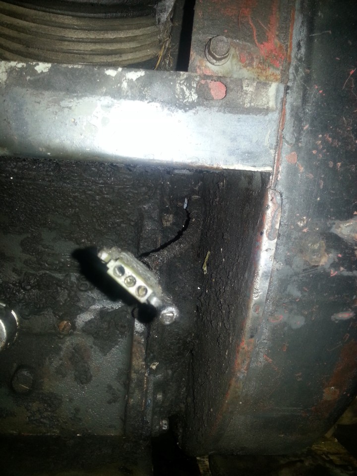
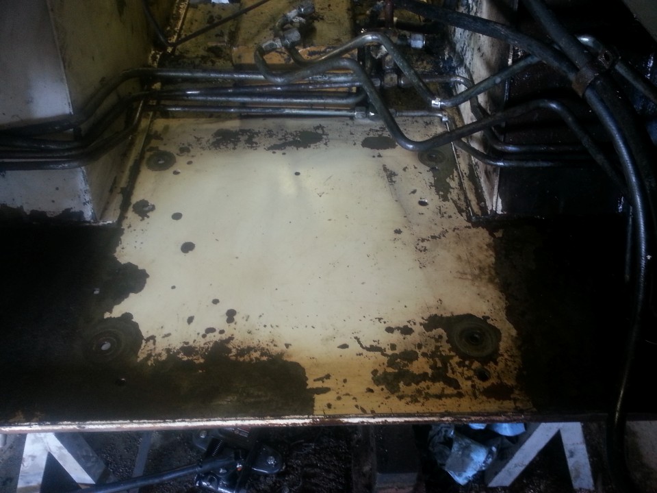
During the removal process, the top left electrical "thingy" in the photo below was ripped off its aluminium base. I sort of banged it back together. I will need to find out what the thing does because there are two of them and one of them seems to be wired into the alternator (magneto). I plan to rewire the machine anyway so whatever it does can be upgraded. I hope.
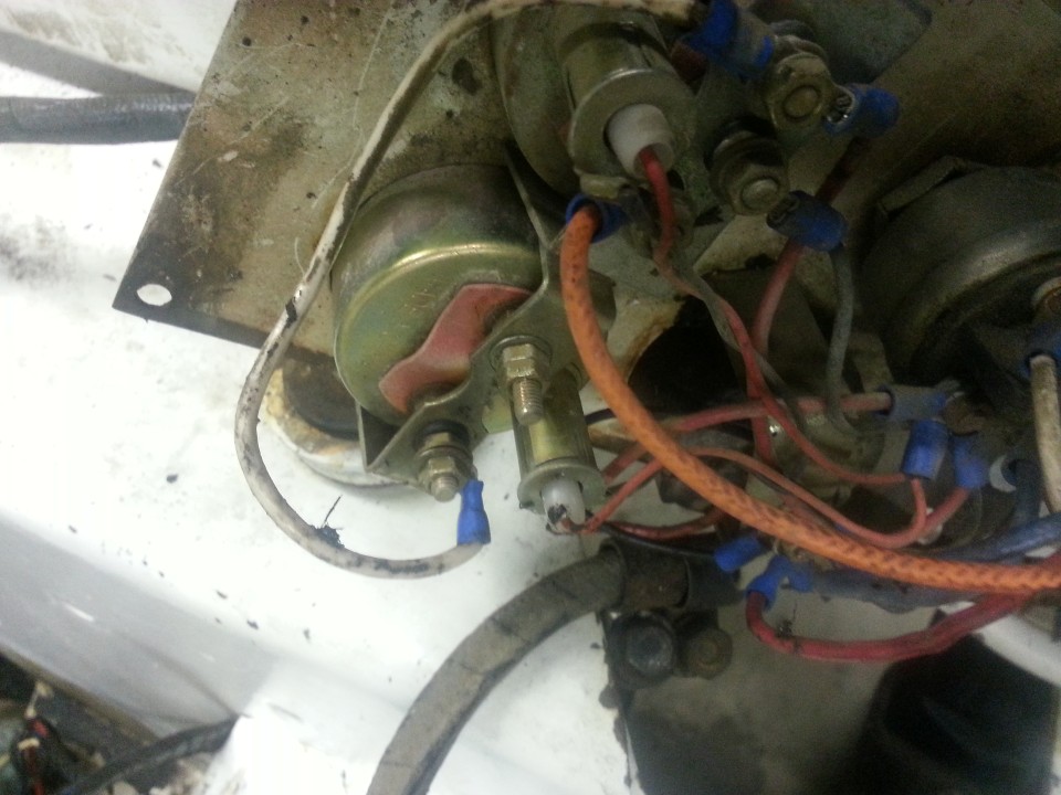
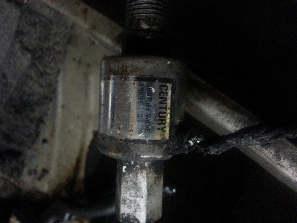
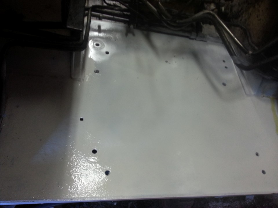
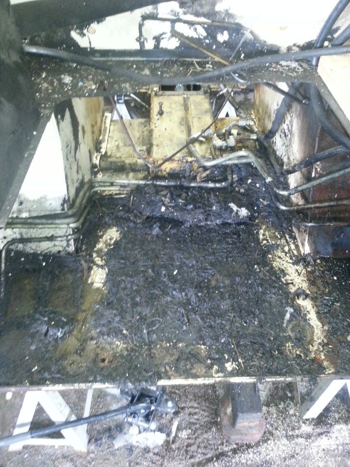
This is what was left inside the almost stripped little machine:
More mulch, and more mulch removal tomorrow.
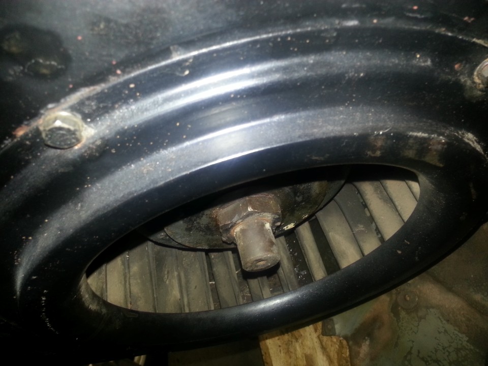
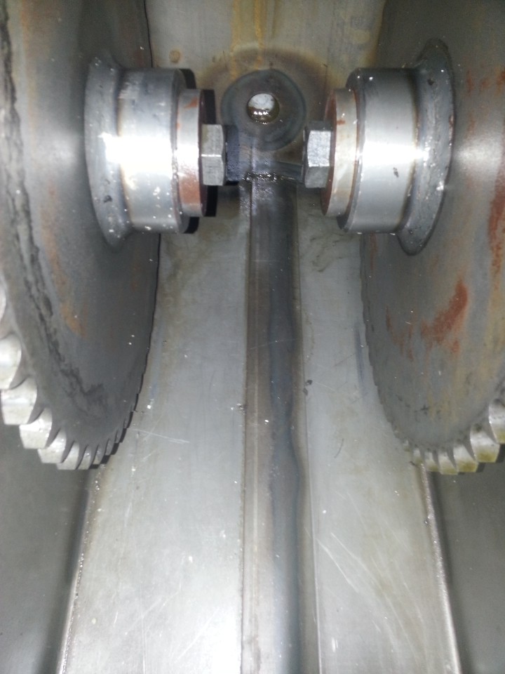
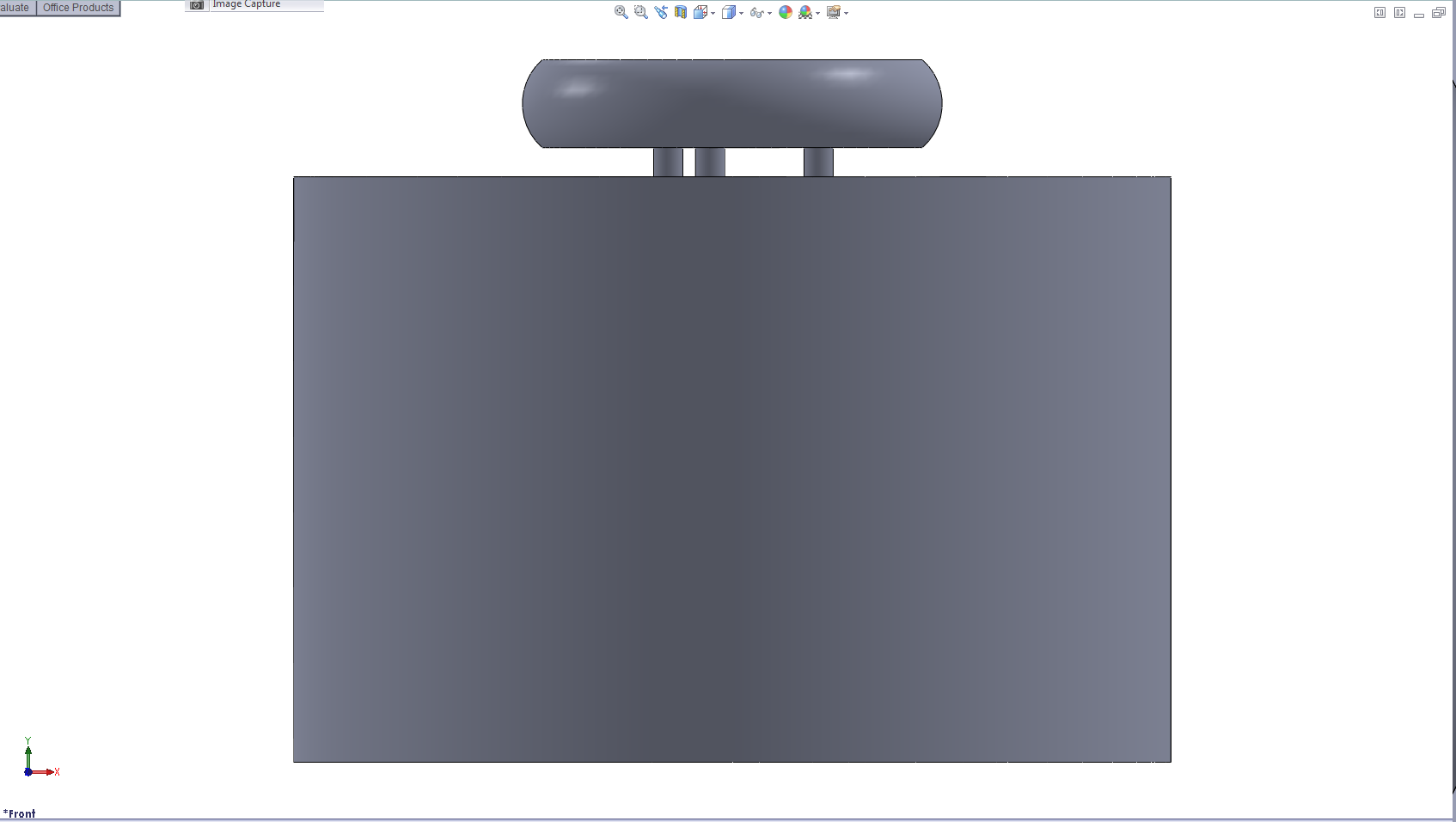
Ok, so I stripped off the universal. The intention was to fit a pulley to the motor side of the universal. This is really the only place that I can see to easily draw power from the motor without serious modification. The intention was to remove the motor interface section, accurately turn it down to accept a taper-lock and then fab a bracket to hold an alternator.
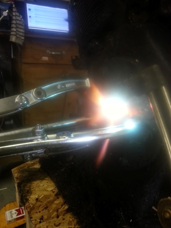
How does one get the thing off???? The largest of my 4 set of 3 puller jaws, under cranking and heat:
did absolutely nothing. I also pounded the coupling when cherry red to try and dislodge it, but nada movement.
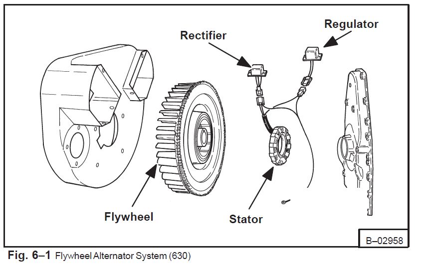
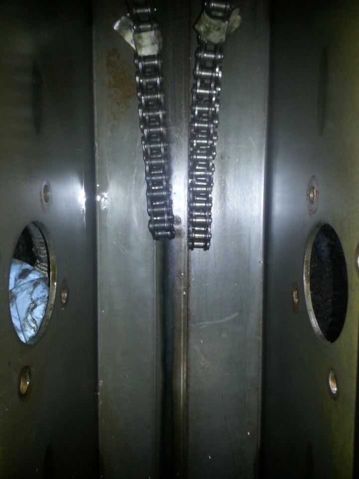
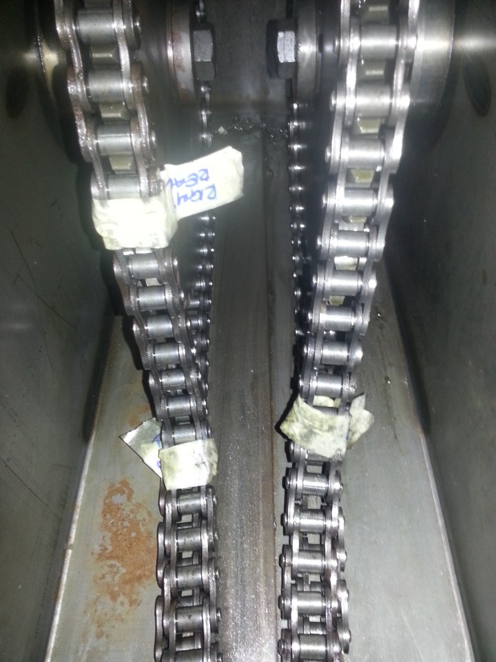
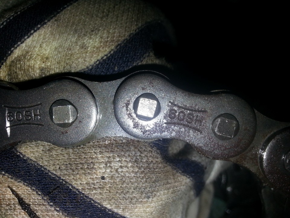
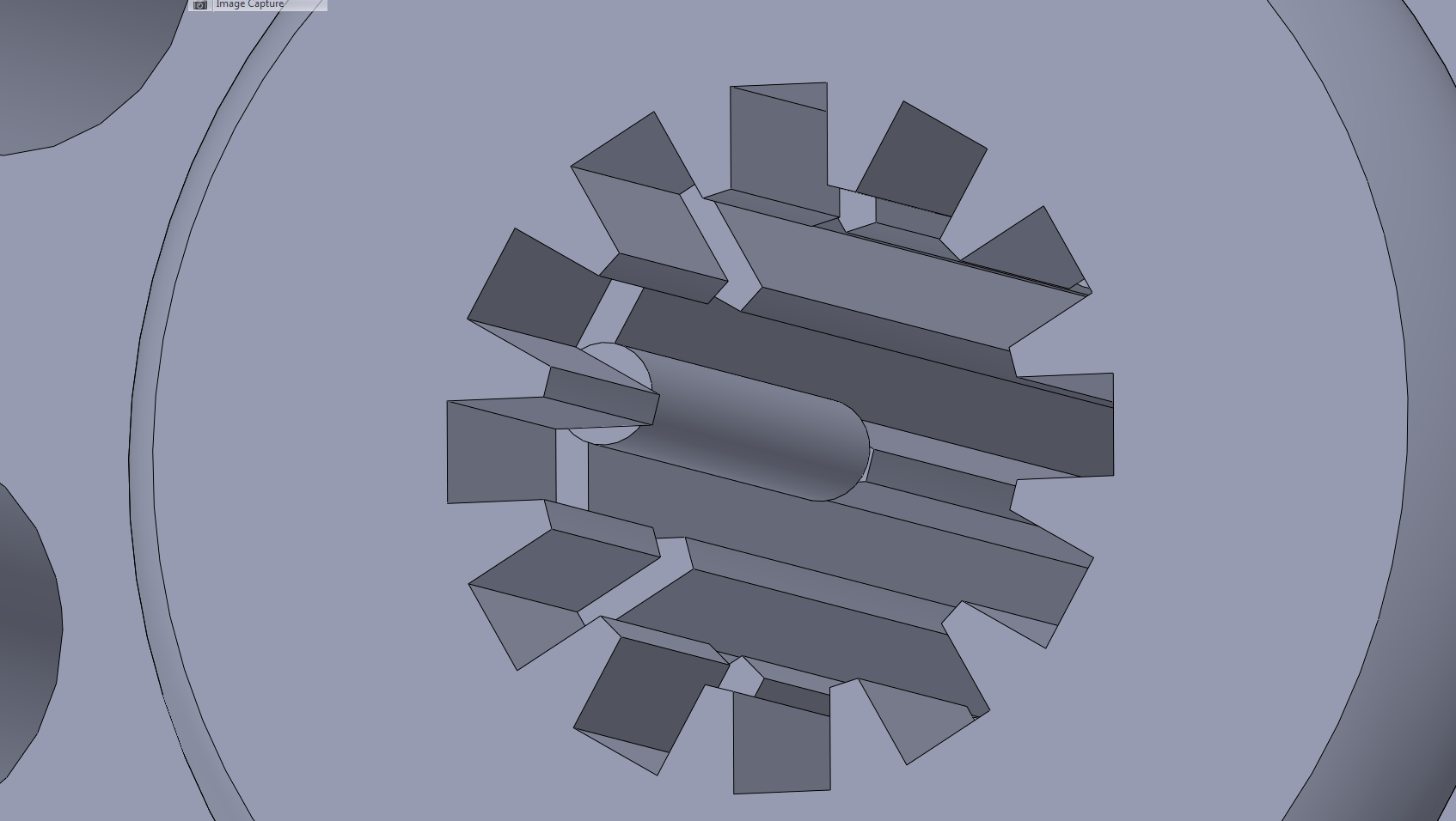
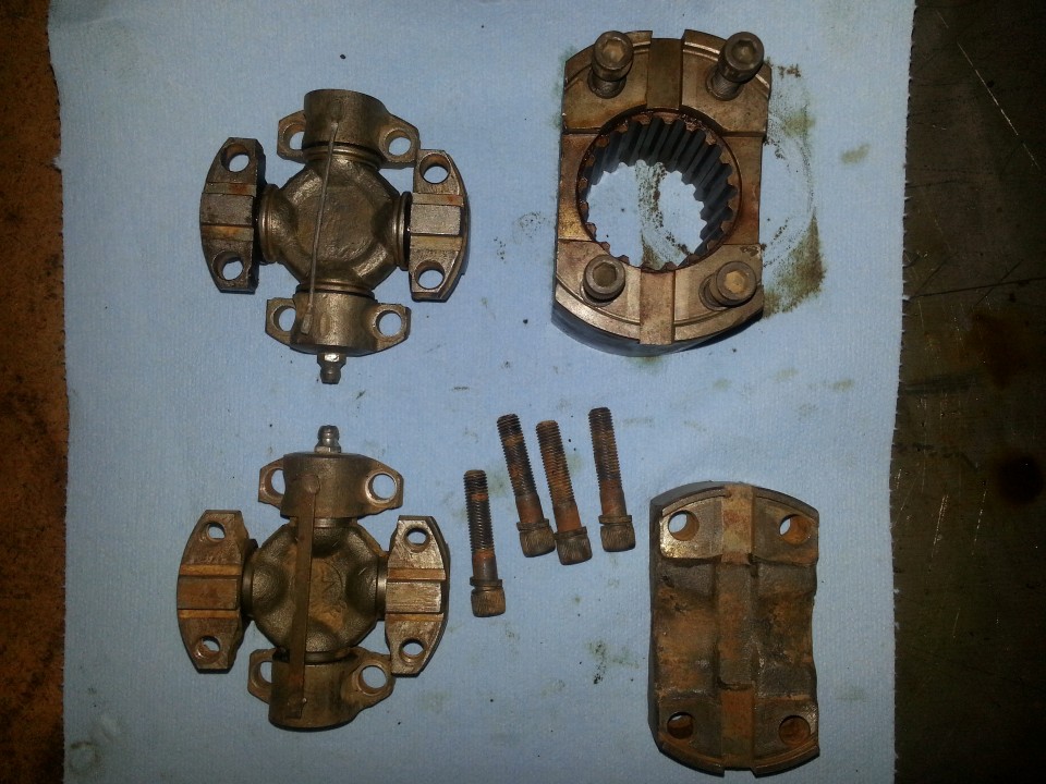
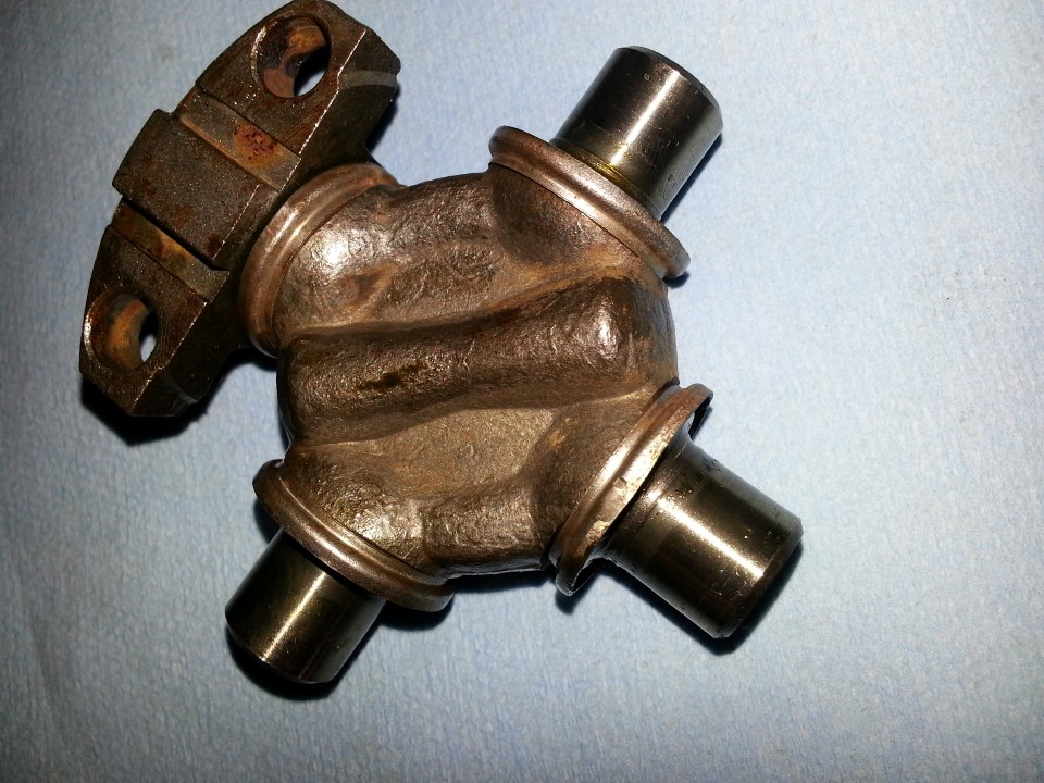
These are the components that make up the universal after cleaning:
Notice that the spiders are different (I assume the newer one has the pathetic, narrower, broken binding strap on the bearings). jerry on 2 Jan suggested inspecting the u-joint intimately, which I hope I have done.
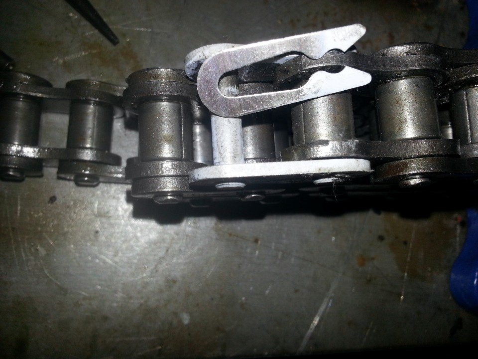
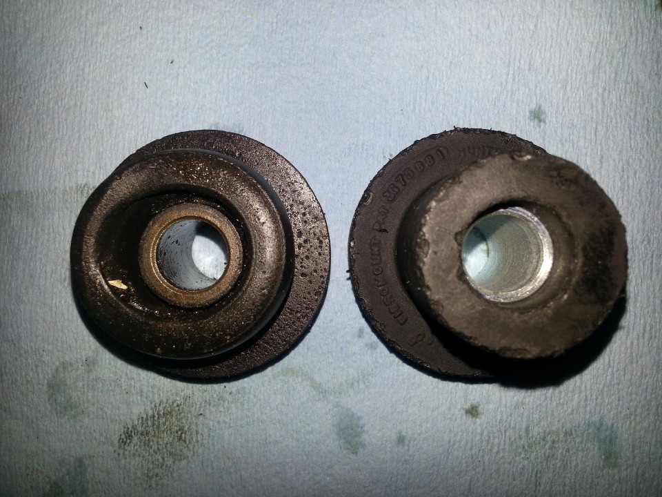
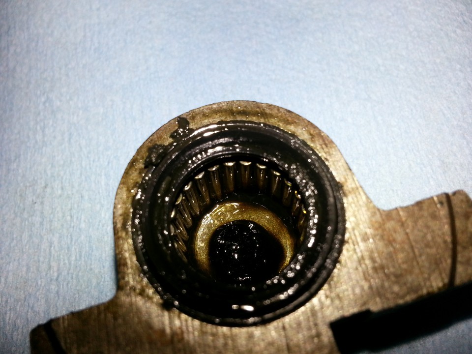
These are representative bearing races:
Dumbo doing the stripping (me) managed to get some solvent into the bearing cup of one of the newer bearings. So the rollers all fell out. 30 infuriating minutes later I had cleaned the cup and managed to get the rollers back:
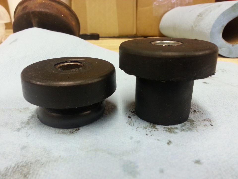
I think this looks quite good. Also, there is very little play in the setup so I am not going to replace more parts.
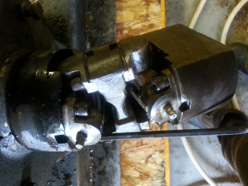
I assembled the whole story and just when tightening the last Allen cap, this:
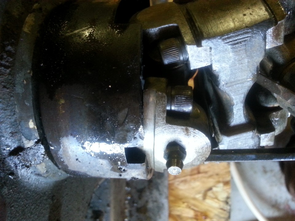
Zoom in to my mistake:
Note to others. The universal has a very slight taper on the bearing cup holder. Tighten both bolts evenly to pull the taper into the cup. Not doing so causes the effect on top left above, where the taper cocks in the cup.
Notice also in the photo two above that I have aligned the grease zerks. This is intentional. I know, with 100% certainty, that when I first want to grease the universal, that its orientation will be so that I cannot get to any one of them. But, at least I know that when, after hours of effort, I get to one, I should be able to get to the other. Hah!
So, there we are. Except:
Any ideas on how to remove the two rusted bolts. Drilling and helicoil seem to be the only solution, but perhaps there is someone else with a more elegant solution?

") a good oxy torch is worth its weight in cold some times.
a good oxy torch is worth its weight in cold some times.