peebeeaitch
Well-known member
- Joined
- Dec 3, 2012
- Messages
- 115
19 Jan 201311 Jan 2013
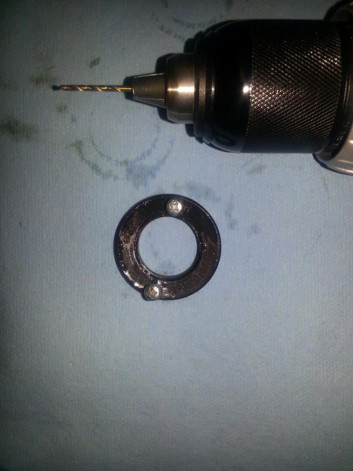
"Used, good condition, 1/4" drive, external Torx E10 deep socket" arrives. Said deep socket does not fit.
12 Jan 2013
Remebering that the sockets I'd seen online, featuring a 12!! point system, fit almost all variations of bolt head shapes, I headed out to the store. Of course, the sets which contained 1/4" drive, 12 socket sets were sold out and after 1 hour of scrumaging, the only way I could find to get a 12!! point 5/16" socket was to buy the set - mind you, on special.
13 Jan 2013
Biblical hangover from the suprise birthday party. No progress.
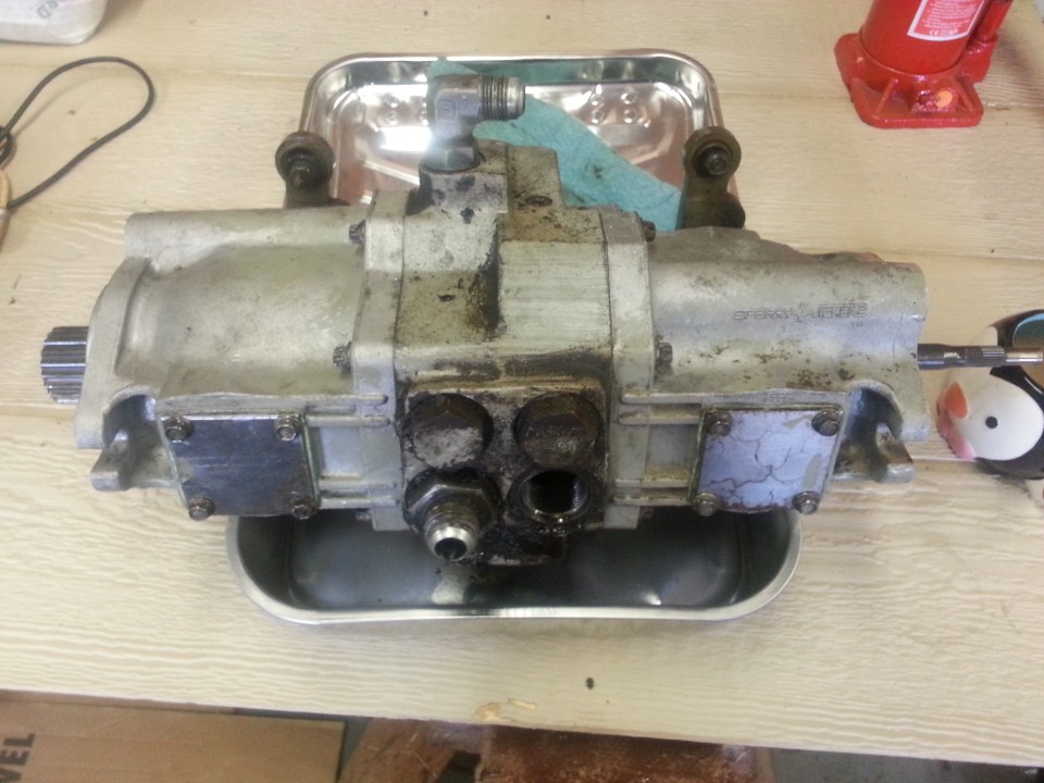
Clearly I needed a press, the sprocket had to come off. Speaking to the chaps at work, they strongly advised against getting a press from a company that imports very inexpensive tools. They suggested I buy a quality item that would last for years. But, they could not guess if 6, 12, 20 or 50 tons would beenough to remove the sporcket from the motor.
I decided to buy an inexpensive, inferior quality press that I now know will not last for years. Simultaneously, I bought a "4 set of 3 puller jaws" set of gear pullers. For the uniformed, that is 4 gear pullers with 3 jaws each. Also, inexpensive.
20 Jan 2013
The set of 4 3 jaw pullers were put to the test removing the sprocket. This failed.
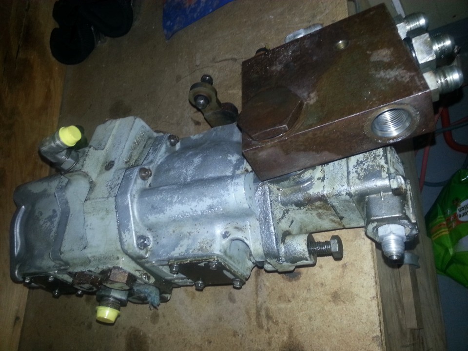
The 12 ton press, and LARGE bearing clam shell I had also bought, were put to the test:
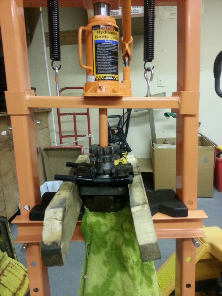
This was after 12 hours under pressure - I had hung on the pressarm and imagine the pressing force to be close to 15-20 tons. Sprocket 1: Press, and clamshell, 0.
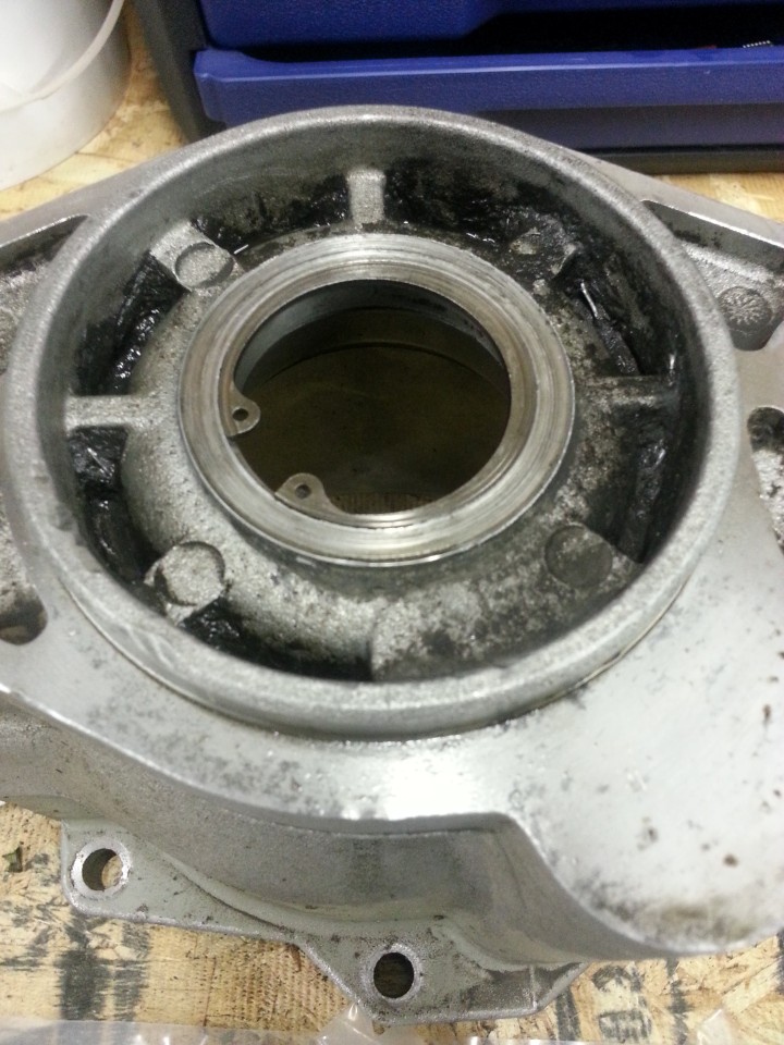
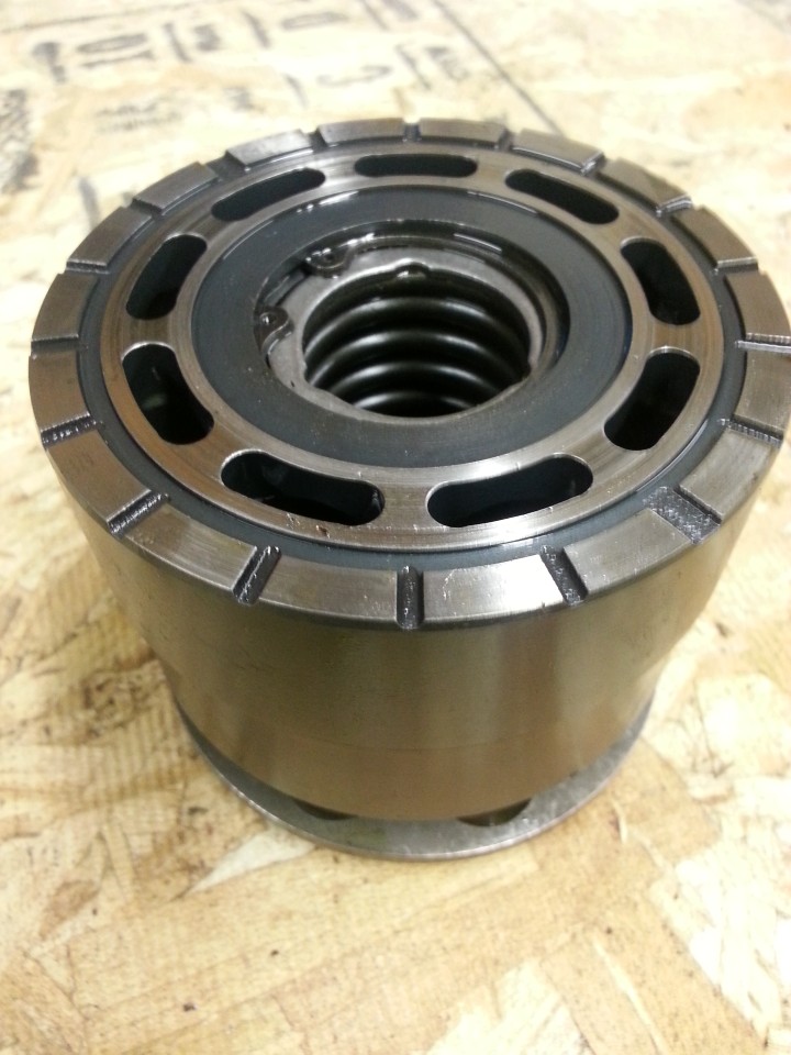
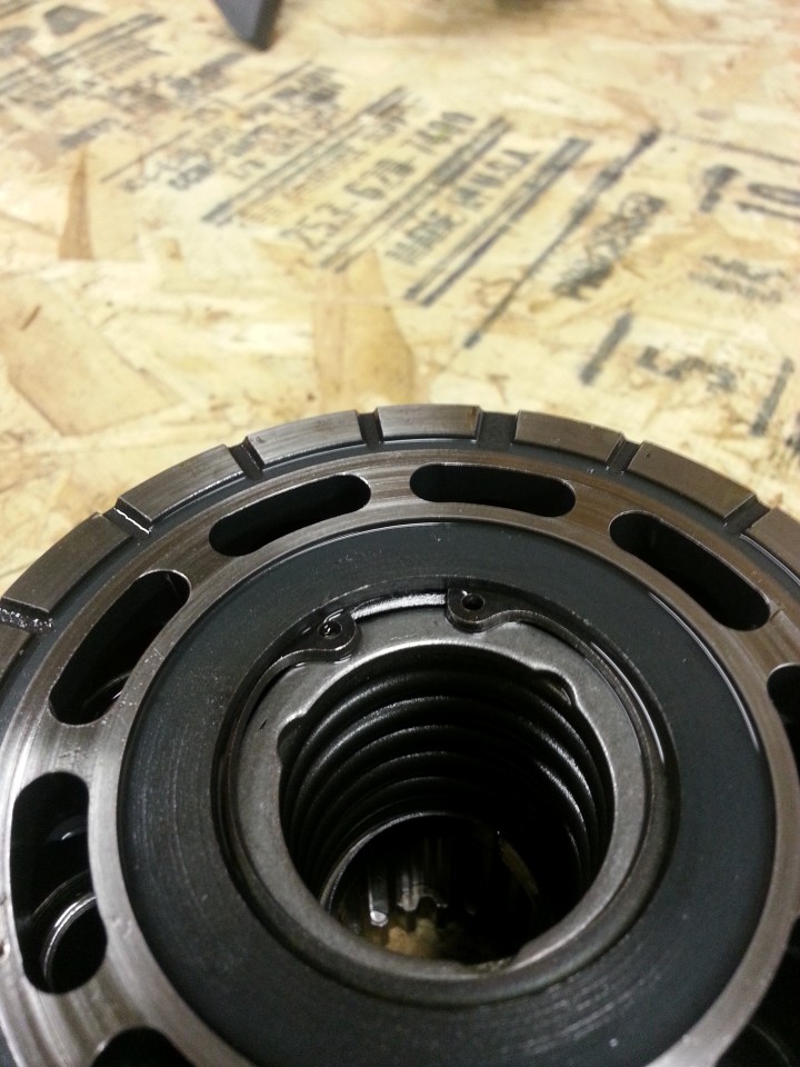
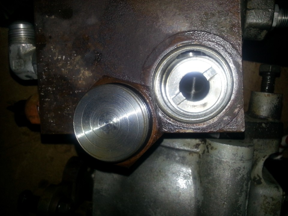
The chaps at work used a quality gear puller, quality gas, quality 200lb sledge hammer and managed to remove the sprocket. Fearing that the other sprocket would also resist, I took it in as well and now it is: Sprocket 1: Huge effort: 2.
") Especially the chain breaker, pretty and the functional ones, i totally agree there!
Especially the chain breaker, pretty and the functional ones, i totally agree there!