OP
OP

Bonez
Well-known member
OK, Ive read that points should be in the fully open position ( assuming TDC ) so if that is correct then I am good to go.... I hope.

.016" is @ the peak of the POINTS CAM lobe. That should be at or near TDC if I'm reading correctly(?) The gap will remain the same regardless of the timing once set. 20* is when they are just breaking (spark) Did you find the plate to be adjustable?So I dove into italthough I was hesitant to do so. Pulled the radiator and muscled the front cover as much as I could, found the timing marks and lined everything up... the first go the points were completely closed so it was 180 out, cranked it around and the gap was too tight so I adjusted it to .016. The spark plugs were also gapped too far so I adjusted them to .025
Now I need to get a battery so I can test the fuel pump and see if it will fire up... I cleaned up the cooling fins on the heads, the radiator is pretty rusted up in the fin area but not leaking, going to treat it to prevent further rusting for the time being.
Now that Im thinking about it.... was I supposed to set the points at .016 on the 20 degree mark or TDC.... as I adjusted it at TDC... hope I didnt goof it... otherwise I know what Im doing tomorrow.
Thanks, After I came in and settled down my mind got racing, and Im like, was I supposed to set the points at the 20* mark or TDC??? Then I re-read the files and the best I got was TDC.... so I was hoping I didnt have to tear this thing back apart as it was a PITA to get to some nuts and bolts besides no room to move the cover. Im afraid to remove some brackets as there is no access to the back side for the nuts and I have seen some YT videos where the nuts fall into the drive chain area and needs fished out... same with the cage bolts, I want to remove the cafe for easier access to work on the stuff but I dont want to get into where I dont need to yet..016" is @ the peak of the POINTS CAM lobe. That should be at or near TDC if I'm reading correctly(?) The gap will remain the same regardless of the timing once set. 20* is when they are just breaking (spark) Did you find the plate to be adjustable?
Just an aside: I've noticed Onan did go to an electronic ignition system for their 2 cyl. engines. Have no idea if it could be retrofitted to their earlier engines but might be worth investigating? If it would work and you could find something in a boneyard; might be worth doing. Otherwise aftermarket would surely be cheaper. Just food for thought.
Didn't see your last post. Yes I think you are good.

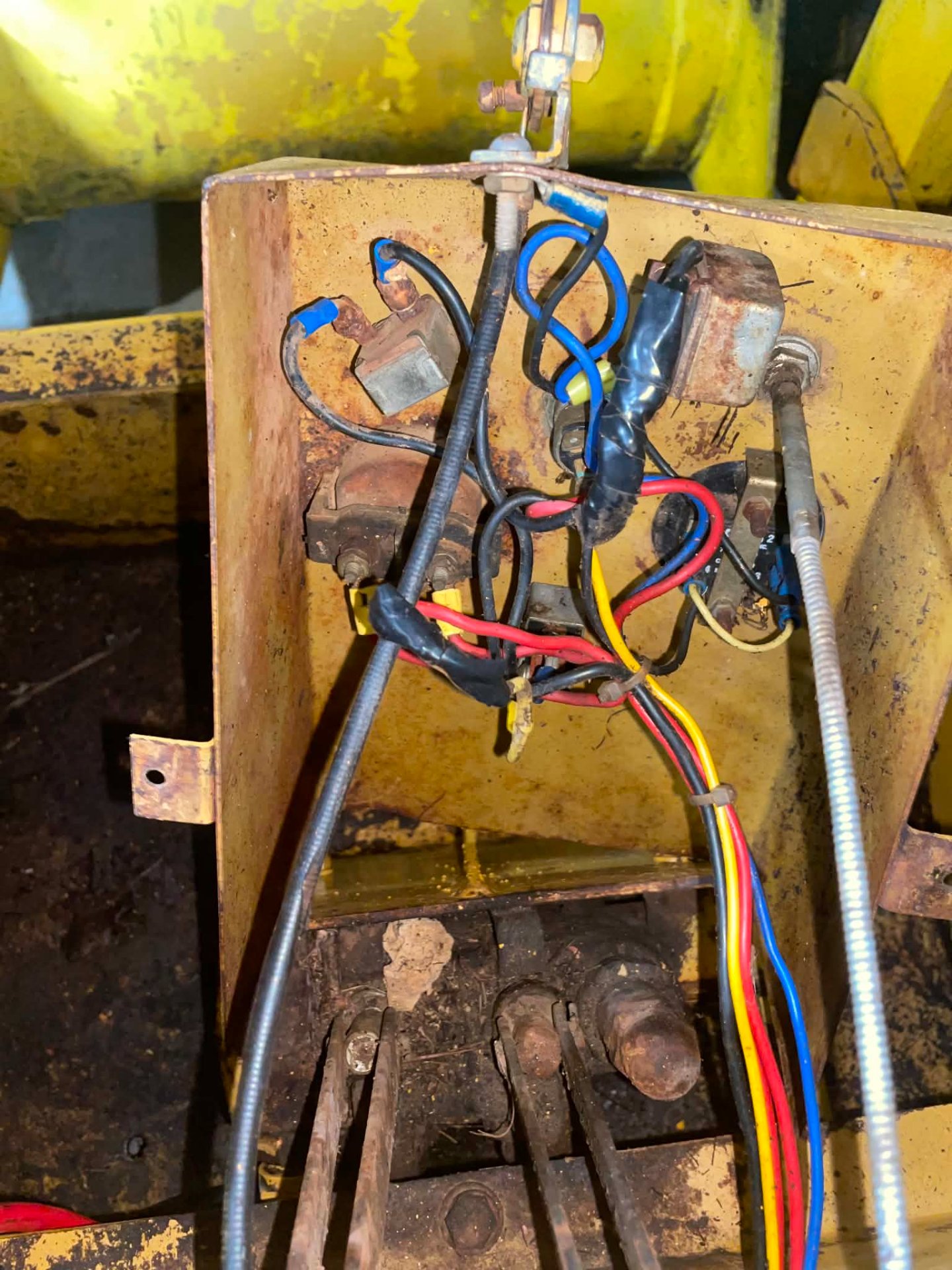
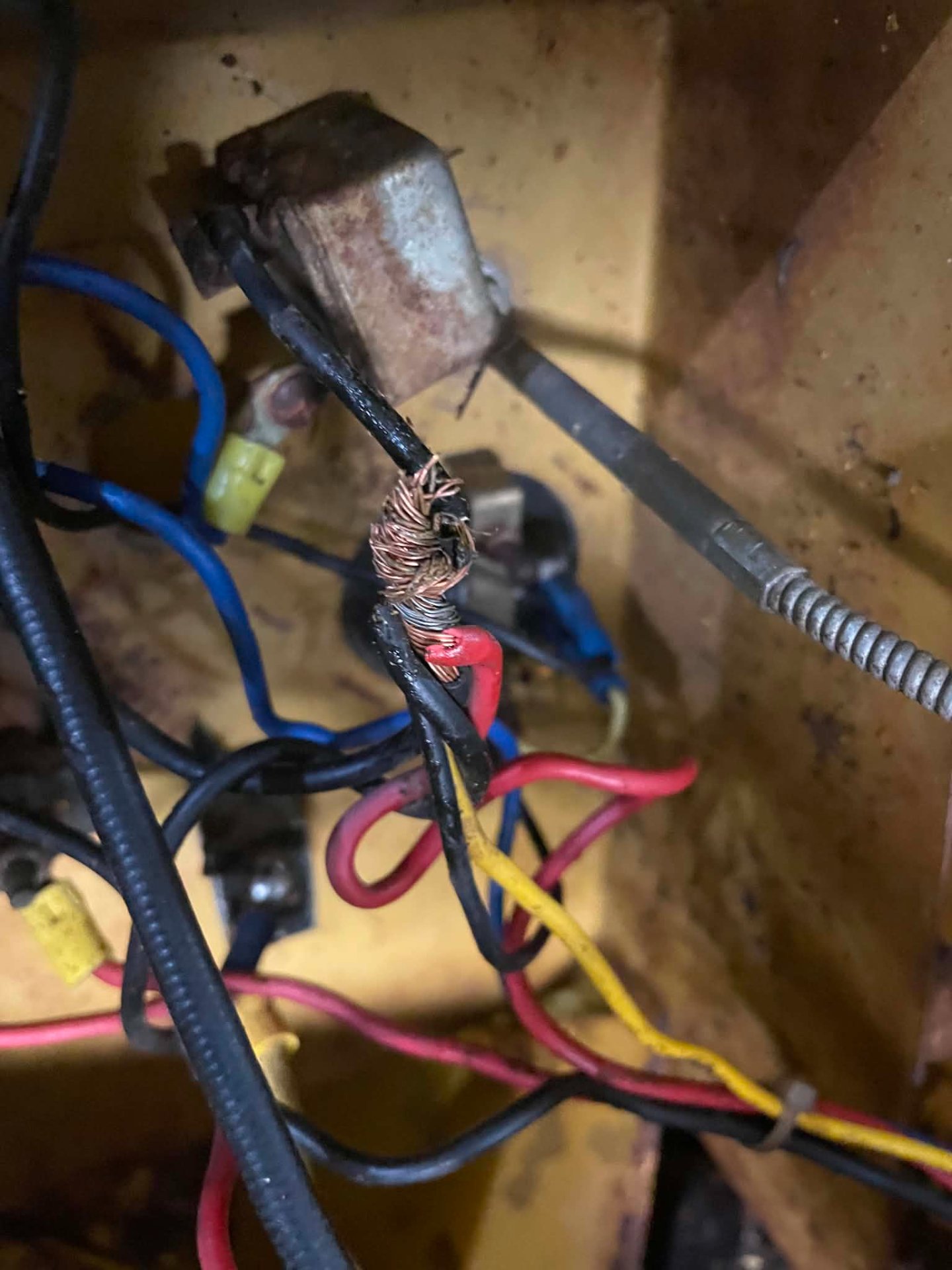
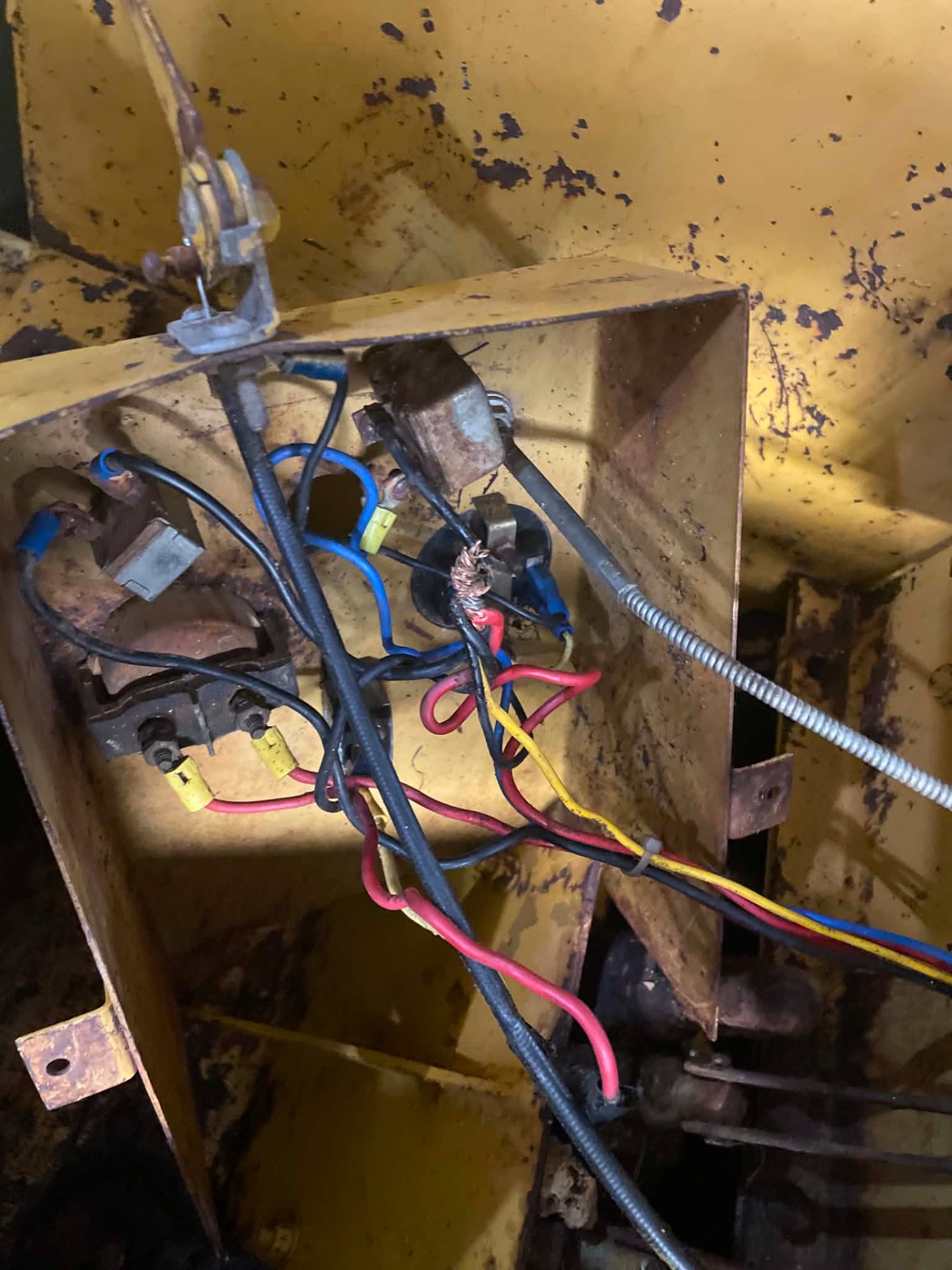
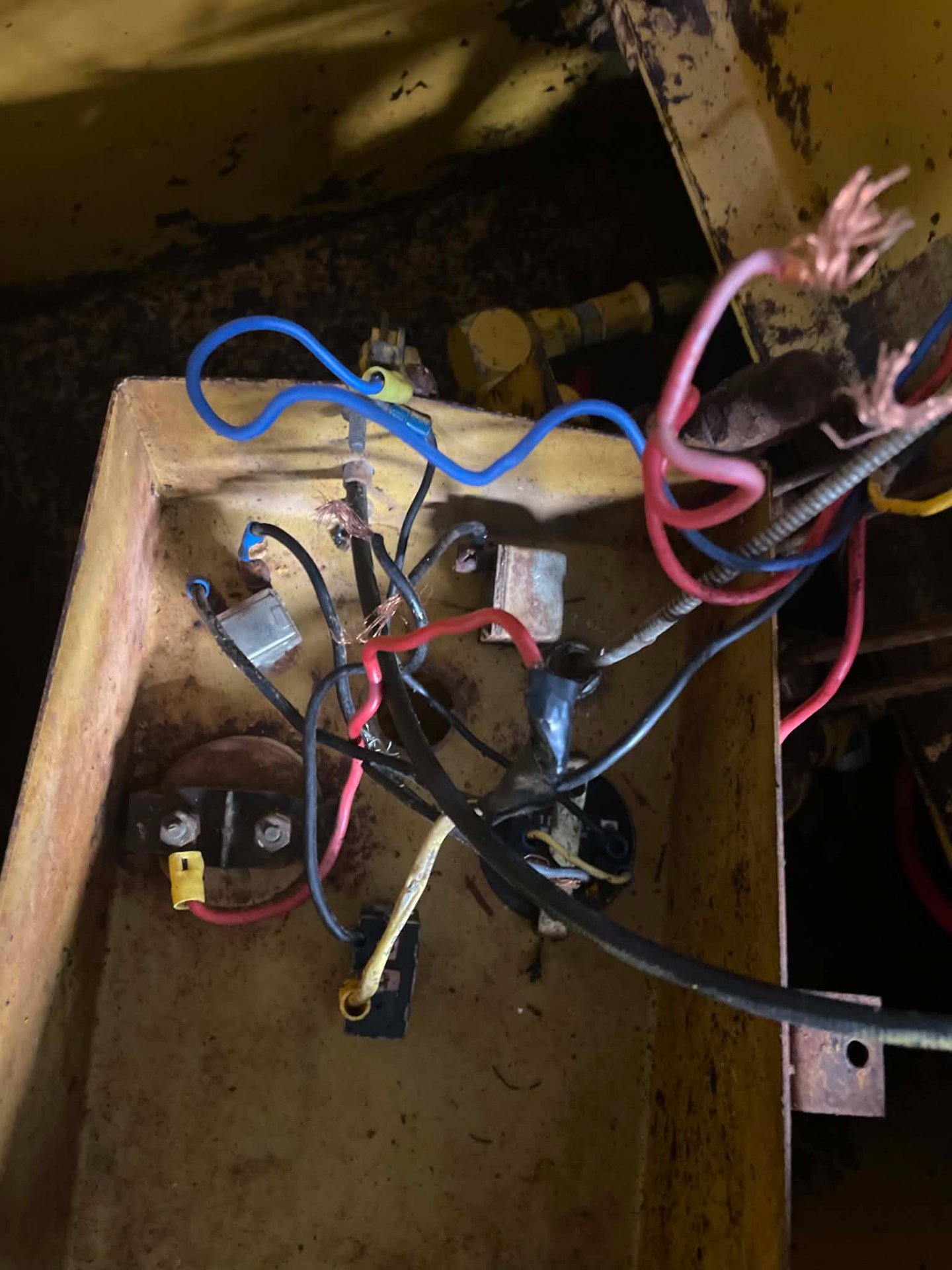
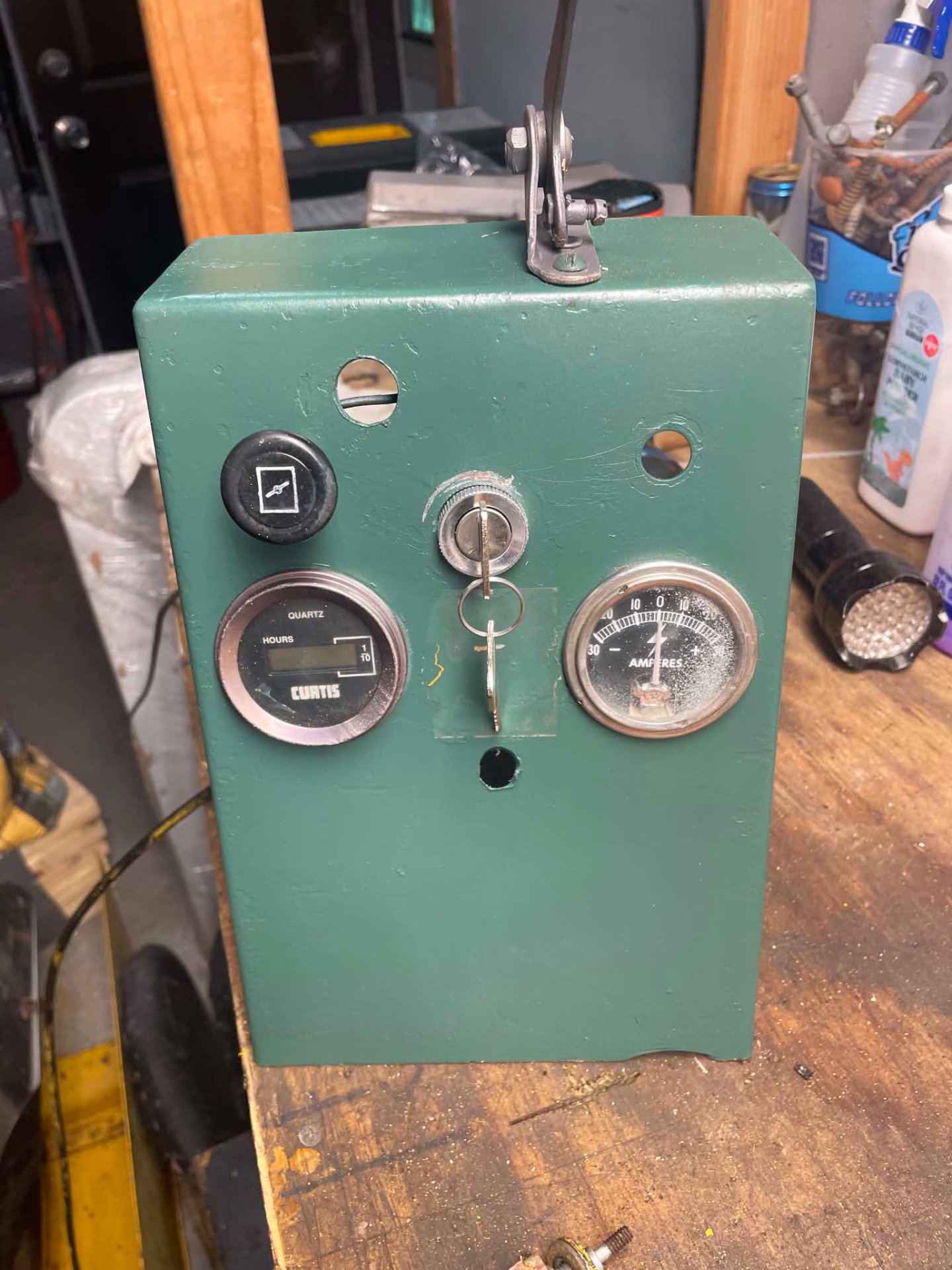
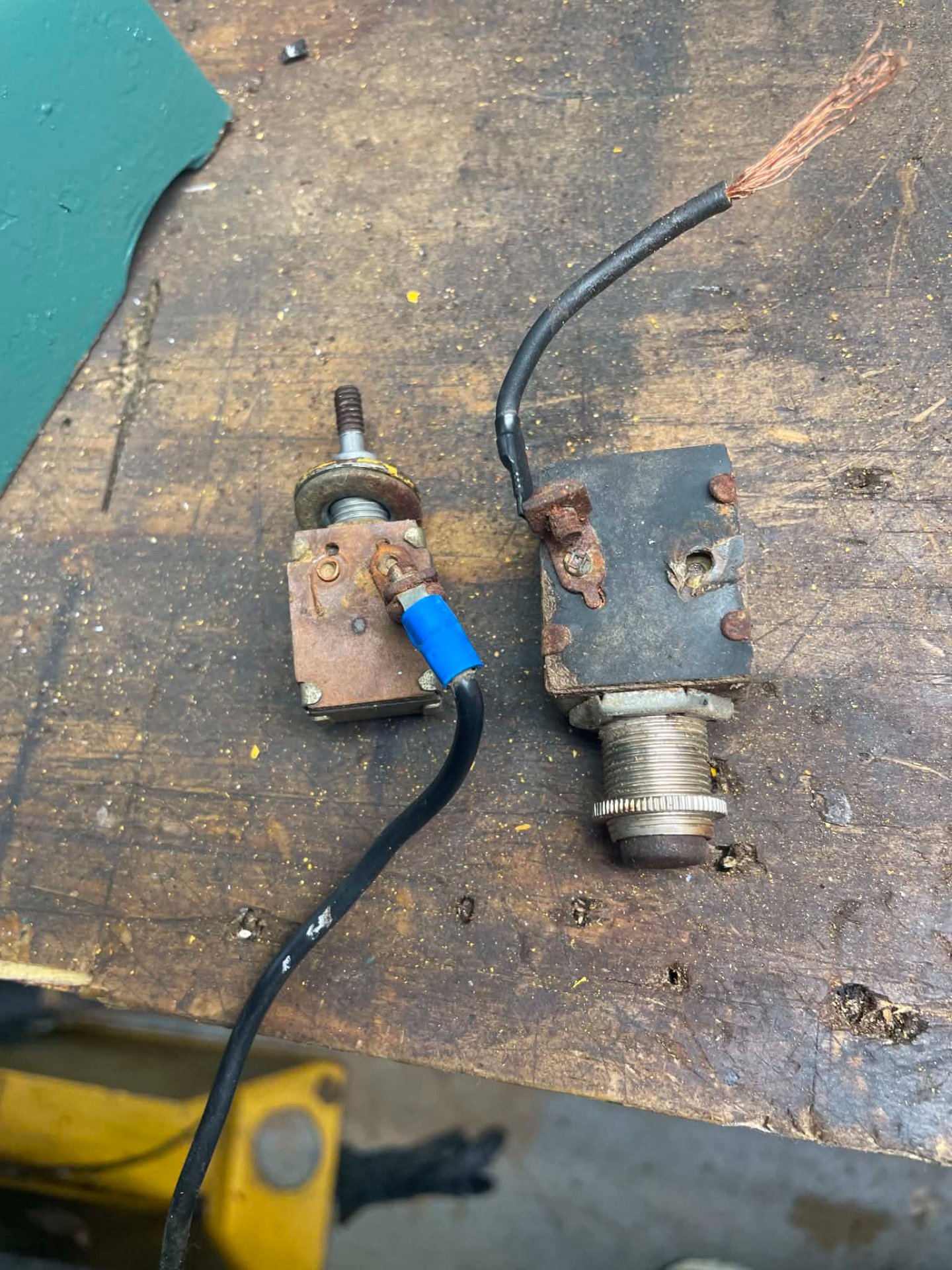
Agreed, besides the key switch was bypassed with a toggle, I bought a new key switch so its secured from unwanted tampering. The ignition switch would stick and the others were corroded pretty bad. As I tried to remove the switches the terminals were breaking off so I just decided to replace them all with new and clean up that rats nest of wires since there are some moving controls behind there that can rub the wires so I will put it in a loom as well for added protection.Tearing the console off to redo those rotted terminals properly instead of just re-taping them is the right call and the weatherproof switches are a nice touch.

Onan 2 cylinder 25hpJust curious what engine does is have in it?
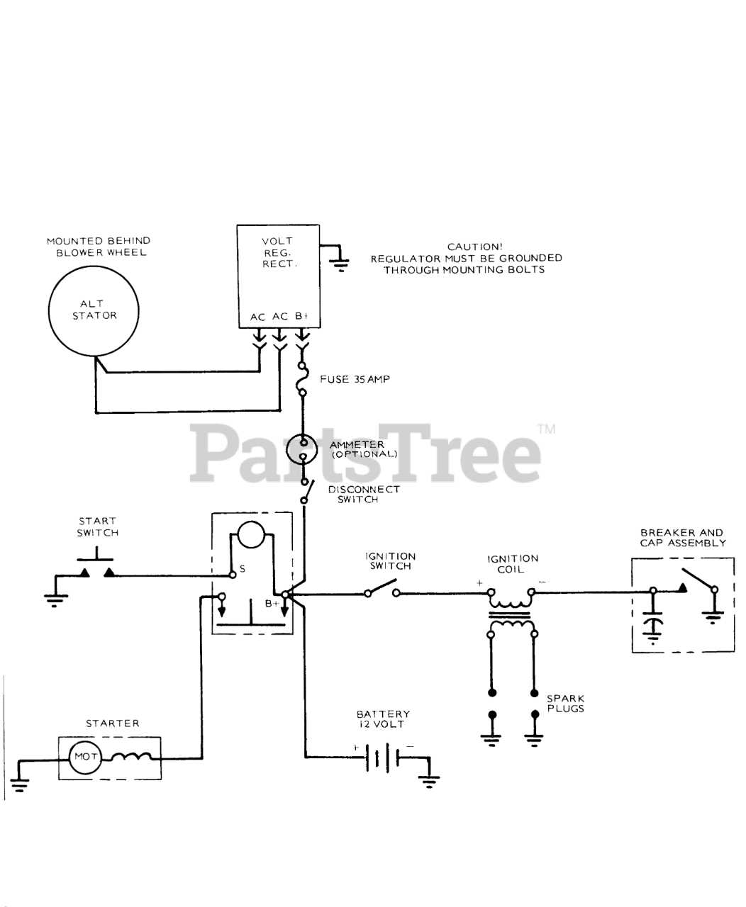
Ok, I;; have to check that, Im not sure if theres a line running there from the rect.The line from the starter solenoid (B+, which is also connected to B+ on the rectifier) charges the battery when the engine is running.
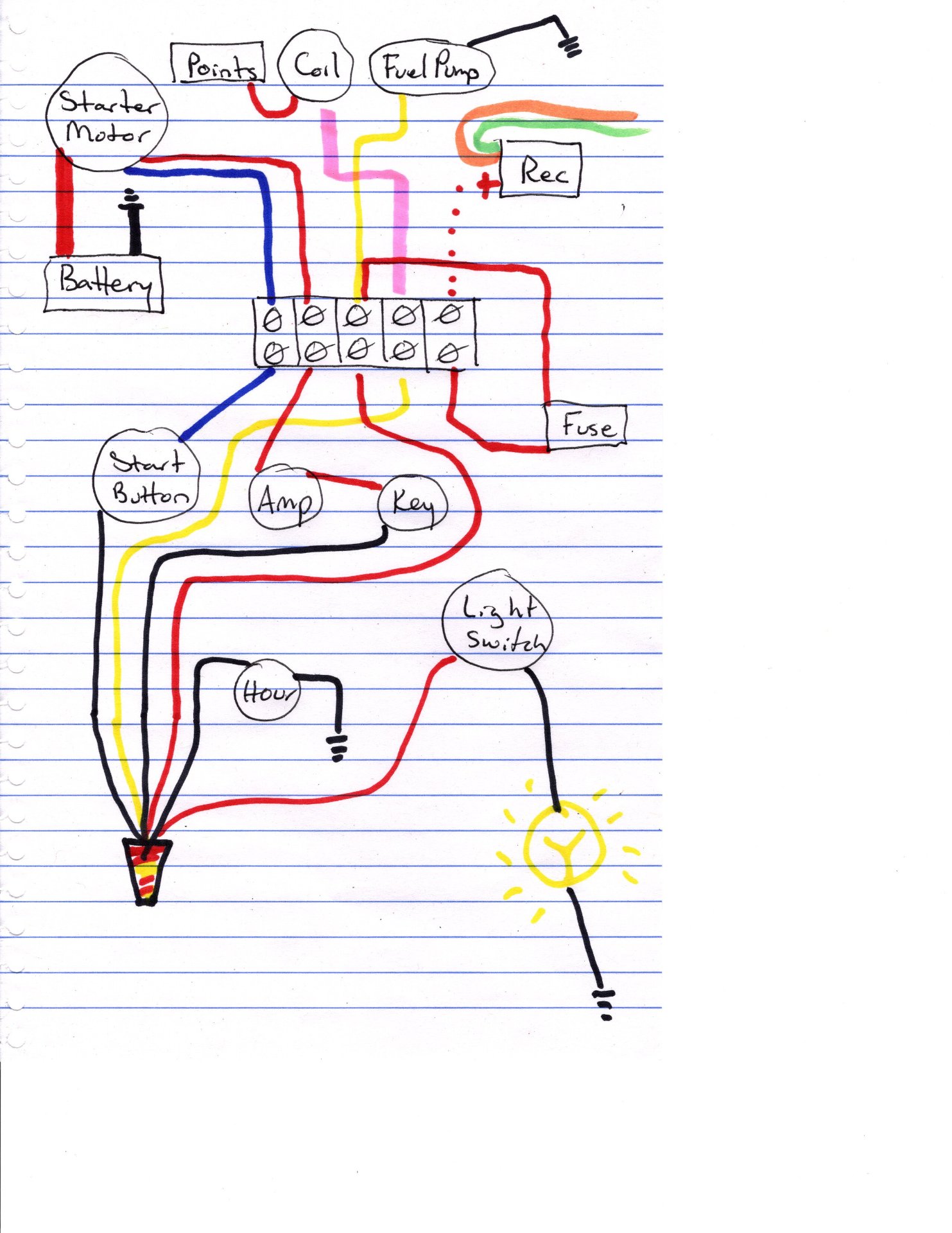
Looks like it should work.Ok, I traced and mapped out the current wiring of the machine, FIL says battery wasnt charging and going dead while using it years ago. Im a bit confused with all the wires that were twisted together ( wire nut drawing ) and where they go if its correct. I couldnt trace the other 2 wires from the rectifier as they went into a plastic sleeve and into the motor somewhere so thats why the 2 neon colors green and orange just end to the right at top. and the points just ground out ... so my question is, is this wiring correct from their respected locations and off the bus bar on top of the motor? Thanks.
* yes the red wire is connected onto the same terminal of the starter with the battery cable
As to the not charging issue; my guess would be a bad regulator. I'm guessing that is using a mechanical regulator. If so you might be able to open it up and check the contacts in it. Could be stuck.Ok, I traced and mapped out the current wiring of the machine, FIL says battery wasnt charging and going dead while using it years ago. Im a bit confused with all the wires that were twisted together ( wire nut drawing ) and where they go if its correct. I couldnt trace the other 2 wires from the rectifier as they went into a plastic sleeve and into the motor somewhere so thats why the 2 neon colors green and orange just end to the right at top. and the points just ground out ... so my question is, is this wiring correct from their respected locations and off the bus bar on top of the motor? Thanks.
* yes the red wire is connected onto the same terminal of the starter with the battery cable
I was pondering the yellow and red wires as to why 2 feeders but probly to carry the current as you stated. I thought to add a relay and a key switch with ignition instead of the button for starting but I think I will leave it as it is for now until I get it running before I confuse myself more with that nest of wires.Looks like it should work.
First off your green and orange go to the stator (AC posts on their drawing)
Everything in the nut will be HOT with key on.
I would suggest a second terminal block at the panel to eliminate that nut and clean things up. A small fuse panel might be better depending on what you may want to add to it. Space permitting of coarse.
Either the red or yellow from nut to block could be eliminated by putting a short jumper on present terminal block. Just be sure to use heavy enough wire to carry both fuel pump and ignition coil.
Move the jumper with the fuse in it to the "feed" side of the block just to save confusion. (both ends)
Assuming you are using a key switch with a start position I would consider running that wire directly either to the starter or engine compartment block. The fewer connections the better on that one I feel. (just remember you need full voltage to coil on "crank")
The only other thing I see is the ammeter and disconnect/key switch are swapped around but don't see where that would matter. Their way actually seems odd to me.
I will check into testing the regulator, Its pretty big so Im not sure what type it is until I pull it later down the road.As to the not charging issue; my guess would be a bad regulator. I'm guessing that is using a mechanical regulator. If so you might be able to open it up and check the contacts in it. Could be stuck.
Could also be the generator needs "exited" especially after sitting so long. You'll need to research that.
I prefer a button myself, but then again I have been called a Neanderthal.I was pondering the yellow and red wires as to why 2 feeders but probly to carry the current as you stated. I thought to add a relay and a key switch with ignition instead of the button for starting but I think I will leave it as it is for now until I get it running before I confuse myself more with that nest of wires.