Gehl 2500 (Hydra Mac 8A) hydrostatic rebuild

vinito

Well-known member
Joined
Nov 19, 2015
Messages
199
Hi Folks.
It's been either just cold or thawed soupy around here for a few weeks and it is likely to be that way for a while. So I figured since I'm not using my little loader anyway it might be very good to take care of the fluid leak from my hydrostat drives and whatever else is discovered in the process. It will be really nice to have drive units I know are in good shape of course, and leaks always suck so fixing that will be a relief too.
So far I've just been researching so I know a little about what I'm getting into. I found a couple sources for parts so I can get seals and gaskets if I don't just source them locally and/or make them myself.
The big good news for me is that there is a cross-reference for these units and the used market will be tons better than I thought I'd have access to. It uses a Sundstrand 15 series U-type drive unit. Turns out that John Deere lawn tractors used these a lot as well as a couple other lesser-known mower/tractors. I have a little digging to do to find out what differences I may encounter, but reportedly, the innards of all these Sundstrand units are identical. Just today I picked up a whole hydrostat drive and tranny from a Deere tractor for a hundred bucks. From what I can see, the cases are identical too. It's still possible (likely?) that some shafts will be a little different and maybe a port or plug would need to be modified to make them interchangeable. But for me it's good just to have the extra unit in hand simply for a "practice" part so I can learn the process of taking it apart as well as getting familiar with and making a parts list for the seals, bearings and gaskets, which should be identical as far as I can tell. This will greatly speed up the process when I'm ready to bite the bullet and dig into the actual drive units on the loader. And if I do it right, I may be able to have a spare drop-in unit at all times.
So I'll be cleaning up the one I bought and disassembling it to inspect things over the next few days. From this I should be able to get a seal and bearing list together and try to source them locally. If shafts are different, I'll make a CAD drawing of them if anyone is interested. Splines are difficult for most guys to do at home so some shafts may be difficult to duplicate because of that. But if making one from scratch can somehow be done I'll show how to do pull that off if I need to do that for myself. To completely adapt the Deere unit to drop into the loader, modifying or making a shaft or two may be necessary and it might also be good information to have if a worn shaft is bad enough to need machining to fix it.
So that's it for today. More coming soon.

 
Sounds interesting and that you have it all under control.
Keep the updates coming.
 
Sounds interesting and that you have it all under control.
Keep the updates coming.
I've got a pretty minor update today.
I've taken the purchased drive unit apart for inspection and to measure and/or get part numbers off the bearings and seals. I've also done a little more research and found that there is a relief valve difference between my Hydra Mac and the JD tractors because of an implement port usage on the JD. It takes the charge pump pressure higher and can send it to implements I guess and the Hydra Mac has a separate pump for that so it has the lower pressure relief valve.
Also, the swash plate on the JD is limited to have less throw for reverse, being a mower and all (which I would never want on my mower either, but whatever). Anyway, that's a simple fix by milling the extra material away off the swash plate yoke thing. Other than those two items, it appears to be identical.
The condition of the purchased drive unit seems to be very excellent with one minor exception. Everything inside is very clean, very tight and very smooth. If nothing else, I got a set of really good parts to repair my machine's drive units if necessary. The input shaft has been buggered up a bit, but I fix that kind of thing for the power plant daily so it will be like new soon. I got most of a parts list together and I'll finish that up tomorrow and try to find a local source for all of that. As a bonus, today I remembered that a friend of mine has a laser cutter so I think rather than purchase the gaskets, I'll just draw them up and have him laser cut them out for me. That will make them cost under $5 in material rather than $75. It's not really worth the effort in efficiency, but it will be kind of fun and I'll be able to upload the file somewhere so others can download and cut their own too if they want.
I'm guessing locally sourcing my own bearing/seal kit will probably run about $75 rather than the $150 I was quoted the other day. Actually it might be half that if I'm lucky.
So here's a couple quick pics just because...
 photo 2_2.jpg
Pic above shows the two fluid ports. One is "in" and the other is the implement port which I will block with a plug if I use this drive. It also is the evidence that the relief valve will not quite be the one I need for my machine.
 photo 1_3.jpg
 
I've got a pretty minor update today.
I've taken the purchased drive unit apart for inspection and to measure and/or get part numbers off the bearings and seals. I've also done a little more research and found that there is a relief valve difference between my Hydra Mac and the JD tractors because of an implement port usage on the JD. It takes the charge pump pressure higher and can send it to implements I guess and the Hydra Mac has a separate pump for that so it has the lower pressure relief valve.
Also, the swash plate on the JD is limited to have less throw for reverse, being a mower and all (which I would never want on my mower either, but whatever). Anyway, that's a simple fix by milling the extra material away off the swash plate yoke thing. Other than those two items, it appears to be identical.
The condition of the purchased drive unit seems to be very excellent with one minor exception. Everything inside is very clean, very tight and very smooth. If nothing else, I got a set of really good parts to repair my machine's drive units if necessary. The input shaft has been buggered up a bit, but I fix that kind of thing for the power plant daily so it will be like new soon. I got most of a parts list together and I'll finish that up tomorrow and try to find a local source for all of that. As a bonus, today I remembered that a friend of mine has a laser cutter so I think rather than purchase the gaskets, I'll just draw them up and have him laser cut them out for me. That will make them cost under $5 in material rather than $75. It's not really worth the effort in efficiency, but it will be kind of fun and I'll be able to upload the file somewhere so others can download and cut their own too if they want.
I'm guessing locally sourcing my own bearing/seal kit will probably run about $75 rather than the $150 I was quoted the other day. Actually it might be half that if I'm lucky.
So here's a couple quick pics just because...

Pic above shows the two fluid ports. One is "in" and the other is the implement port which I will block with a plug if I use this drive. It also is the evidence that the relief valve will not quite be the one I need for my machine.
Life intrudes and I haven't had much time to work on this for a couple weeks. But today I finally have a block of time to dig into this rebuild again. I have studied the above drive pretty well and locally sourced all the seals and most of the bearings. I found that one bearing pair is odd & rare. It may be available from Deere or some Sudstrand suppiers, but if I simply bore out their pockets from 15/16 to 24mm (.937 to .945) it will accommodate a standard inexpensive bearing. I'll have to bore the valve plates to suit this too but all this is simple.
First I plan to remove the drives from the machine and disassemble them to see if they use the same odd bearing. If they do, I think the minor modification will be just fine, but there's an outside chance that they aren't identical inside and possibly use different parts. So that's the next order of business - crack open the machine's drives and finalize my parts list so they can be rebuilt to "new" condition. There's also a chance that the bearings are OK, but in my mind I kind of think it would be a shame to dig that far in and not replace all the easy parts since I'm already there.
As a side note, I also took a chance and bought some new wheels and tires for the machine. The old tires were rotted (probably original) and two wouldn't hold air no matter what I tried. I fixed one which lasted for a couple weeks, but suddenly it started going flat within a few hours again. Also, they are 13" and those are hard to find a good "tready" tire to fit, and that will likely get worse over time, thus the need for new 12" wheels . I always hated having to deal with flat tires every time I use a car, lawnmower, wheelbarrow or whatever and I'll really like just counnting on the tires being ready to go when I want to use the machine.
Here's a quick pic of them. New on the front, old on the rear. They did just bolt right up to fit fine and need no "customizing" to make them fit. I'm not sure if, compared to the original tires, the deep tread will cause me grief or whether I'll like them in the end, but I hope they will be OK. It seems that every "real" skidsteer I see in person or in pictures has a similar tire tread, so I'm guessing it will be just fine. They look good, at least to my eyes.
 photo tires1.jpg
 
Life intrudes and I haven't had much time to work on this for a couple weeks. But today I finally have a block of time to dig into this rebuild again. I have studied the above drive pretty well and locally sourced all the seals and most of the bearings. I found that one bearing pair is odd & rare. It may be available from Deere or some Sudstrand suppiers, but if I simply bore out their pockets from 15/16 to 24mm (.937 to .945) it will accommodate a standard inexpensive bearing. I'll have to bore the valve plates to suit this too but all this is simple.
First I plan to remove the drives from the machine and disassemble them to see if they use the same odd bearing. If they do, I think the minor modification will be just fine, but there's an outside chance that they aren't identical inside and possibly use different parts. So that's the next order of business - crack open the machine's drives and finalize my parts list so they can be rebuilt to "new" condition. There's also a chance that the bearings are OK, but in my mind I kind of think it would be a shame to dig that far in and not replace all the easy parts since I'm already there.
As a side note, I also took a chance and bought some new wheels and tires for the machine. The old tires were rotted (probably original) and two wouldn't hold air no matter what I tried. I fixed one which lasted for a couple weeks, but suddenly it started going flat within a few hours again. Also, they are 13" and those are hard to find a good "tready" tire to fit, and that will likely get worse over time, thus the need for new 12" wheels . I always hated having to deal with flat tires every time I use a car, lawnmower, wheelbarrow or whatever and I'll really like just counnting on the tires being ready to go when I want to use the machine.
Here's a quick pic of them. New on the front, old on the rear. They did just bolt right up to fit fine and need no "customizing" to make them fit. I'm not sure if, compared to the original tires, the deep tread will cause me grief or whether I'll like them in the end, but I hope they will be OK. It seems that every "real" skidsteer I see in person or in pictures has a similar tire tread, so I'm guessing it will be just fine. They look good, at least to my eyes.
Well true to form, once I got into it a bit, I found a lot more I need to do while I'm in there. The floor pan has an inch thick coat of muck.
 photo pan1.jpg
The chain oil sumps are only half full and contain a mixture of this muck, old oil and water. Nice recipe to bugger a chain if it's not already. A cursory look says the sprockets might be OK but the chain was near the end of the travel of the adjustment slot, so it may need replacing anyway. Historically I have found that half the time, if the chain is worn out the sprockets are too. We'll see how that shakes out.
At least this is a good time to replace this stuff if it needs it. It sure will be nice and snug once I'm back together. It's a little frustrating that these kinds of projects follow this same regression every single time I try, but I guess that also means it's not unexpected too so...
Tomorrow I think I'll run the hydrostats down to work since it's less cluttered and the parts cleaner there is better than mine. I'll make a thorough assessment of both drives and let you all know how that goes.
"Sand the floor"
 
Well true to form, once I got into it a bit, I found a lot more I need to do while I'm in there. The floor pan has an inch thick coat of muck.

The chain oil sumps are only half full and contain a mixture of this muck, old oil and water. Nice recipe to bugger a chain if it's not already. A cursory look says the sprockets might be OK but the chain was near the end of the travel of the adjustment slot, so it may need replacing anyway. Historically I have found that half the time, if the chain is worn out the sprockets are too. We'll see how that shakes out.
At least this is a good time to replace this stuff if it needs it. It sure will be nice and snug once I'm back together. It's a little frustrating that these kinds of projects follow this same regression every single time I try, but I guess that also means it's not unexpected too so...
Tomorrow I think I'll run the hydrostats down to work since it's less cluttered and the parts cleaner there is better than mine. I'll make a thorough assessment of both drives and let you all know how that goes.
"Sand the floor"
Looking good, well not the pile of muck that you need to clean up.
 
Well true to form, once I got into it a bit, I found a lot more I need to do while I'm in there. The floor pan has an inch thick coat of muck.

The chain oil sumps are only half full and contain a mixture of this muck, old oil and water. Nice recipe to bugger a chain if it's not already. A cursory look says the sprockets might be OK but the chain was near the end of the travel of the adjustment slot, so it may need replacing anyway. Historically I have found that half the time, if the chain is worn out the sprockets are too. We'll see how that shakes out.
At least this is a good time to replace this stuff if it needs it. It sure will be nice and snug once I'm back together. It's a little frustrating that these kinds of projects follow this same regression every single time I try, but I guess that also means it's not unexpected too so...
Tomorrow I think I'll run the hydrostats down to work since it's less cluttered and the parts cleaner there is better than mine. I'll make a thorough assessment of both drives and let you all know how that goes.
"Sand the floor"
Vinito - found a link that you may be interested, contains a bunch of Gehl manuals and parts books.
http://pdf.germanbliss.com/
http://pdf.germanbliss.com/HL2500ASkidSteerPartsManual.pdf
Cheers - SR
 
Well true to form, once I got into it a bit, I found a lot more I need to do while I'm in there. The floor pan has an inch thick coat of muck.

The chain oil sumps are only half full and contain a mixture of this muck, old oil and water. Nice recipe to bugger a chain if it's not already. A cursory look says the sprockets might be OK but the chain was near the end of the travel of the adjustment slot, so it may need replacing anyway. Historically I have found that half the time, if the chain is worn out the sprockets are too. We'll see how that shakes out.
At least this is a good time to replace this stuff if it needs it. It sure will be nice and snug once I'm back together. It's a little frustrating that these kinds of projects follow this same regression every single time I try, but I guess that also means it's not unexpected too so...
Tomorrow I think I'll run the hydrostats down to work since it's less cluttered and the parts cleaner there is better than mine. I'll make a thorough assessment of both drives and let you all know how that goes.
"Sand the floor"
On the bottom of the machine, there is a drain plug in each chain /sprocket well. We pulled the plugs out of my brothers and that lets the dirt oil and water drain out. The argument can be made without the plugs dirt can get in. And it probably does, but with out the plugs we have far less problems than when they were in. The problem we had the most was with water/ melted snow that turned to ice and everything locked up tight until we thawed it out. A long laborious process if it is out doors. Those plugs can be a bear to get out as they tend to seize in because of the dirt and water the hold in. You will also fund it MUCH easier to wash it as nor the water and dirt can just drain out.
 
On the bottom of the machine, there is a drain plug in each chain /sprocket well. We pulled the plugs out of my brothers and that lets the dirt oil and water drain out. The argument can be made without the plugs dirt can get in. And it probably does, but with out the plugs we have far less problems than when they were in. The problem we had the most was with water/ melted snow that turned to ice and everything locked up tight until we thawed it out. A long laborious process if it is out doors. Those plugs can be a bear to get out as they tend to seize in because of the dirt and water the hold in. You will also fund it MUCH easier to wash it as nor the water and dirt can just drain out.
Thanks for the links. I did find and download that manual as well as the owner's manual shortly after I bought the loader. I also bought a decent service manual for it off eBay and though it's not terribly thorough compared to some I've seen, it does include a lot of useful things that aren't even touched on in the free downloads, so it was well worth it.
Wow Mark. You very well could be correct, but my reflexes certainly scream NOT to leave those drain plugs out. If I don't have to install new chains and sprockets (less to lose if something doesn't work out) then what I could try is leaving the plugs out on one side so I can check them out after a couple years and see if there is any difference from one side to the other. Seems like those wells might be good for containing a little bit of oil bath for the chains, but I could be totally wrong about that for all I know. I can say that at least it seems like keeping the chains oiled can't be a bad idea.
My dad has an older Mustang skid steer that he leaves at his house in town. He uses it 99% of the time for snow and maybe dumping a couple loads of mulch each year. He took the plugs out and even drilled a couple extra holes to allow snow and water to drain out. Probably not the best idea for a machine you are going to dig with, but he's been happy with it like that for at least the last 10 years.
 
My dad has an older Mustang skid steer that he leaves at his house in town. He uses it 99% of the time for snow and maybe dumping a couple loads of mulch each year. He took the plugs out and even drilled a couple extra holes to allow snow and water to drain out. Probably not the best idea for a machine you are going to dig with, but he's been happy with it like that for at least the last 10 years.
Posted this on the rebuild thread but shoulda put it here...
I was determined to make a little progress today, so I decided to start working on the hydrostat rebuld again. A while back I took apart the "extra" one I acquired, mostly for a little practice and to get a parts list together. Bonus that it turned out to be in really good condition with hardly any wear at all, so lots of good parts if I needed them. Today I took apart the two that came from the loader to make a good inspection. Turns out they weren't too bad. Just a couple parts that I think I'll go ahead and switch out with the new one, but those parts can be made well enough for later. I just figure I'll put the best of the crop back in the loader and the rest will be benched unless I need them.
I have some decent lapping equipment - small lapping plate and a good range of grits of compounds. So just to make it simple I picked 400 and 800 for rough and finish. I got through all but one cylinder assembly and it's all looking pretty good with just minimal material removal. This thing ought to scoot around like new.
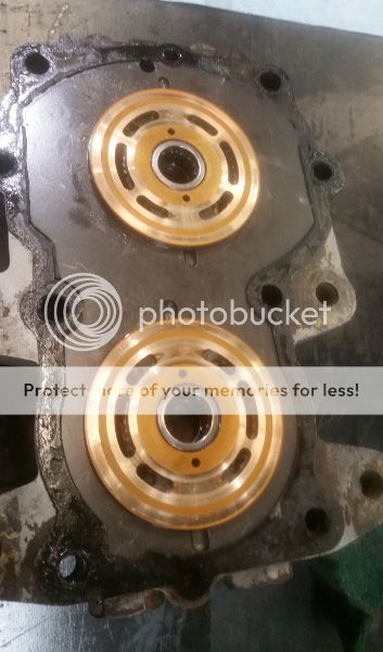
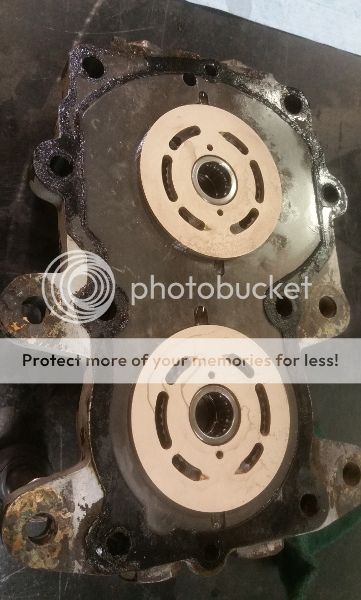
Here's a sample of a couple parts. It's the valve plates for one of the hydrostats.
Before on left: Not too bad but there is some wear just deep enough reduce performance slightly.
After lapping on right: The spots is just "drip" left after the solvent rinse dried. It's actually a flawless, flat bronze surface now. Sure looks purdy.
 photo Lap 1.jpg. .  photo Lap 2.jpg
So there is a small pile of other stuff that has been lapped nicely. One more session of lapping and all the parts will be ready. I'll just have to clean the case, polish the seal areas of the shafts, install new bearings, seals and gaskets (all of which I've already amassed) and these babies will be ready to fill with oil and put into service.
I don't have pictures, but I've rebuilt the check and relief valves for one of the hydrostats already. They aren't bad at all and work like new now. As usual, the first one always takes longer so the other set will be quick and easy. It's really just replacing O-rings as long as the rest survives inspection, but you have to turn off a ridge using a lathe to access a cap, then TIG tack-weld that back on once it's all stacked back together. Still, it's pretty simple. I'll get some pictures of the next attempt.
All in all, these particular little hydrostats are extremely simple to work with without scrimping on quality. I was very surprised of the condition of them considering they've been rode hard and put away wet since somewhere around 1974. This next phase should certainly outlast me.
Boy I'll tell ya. It sure is nice starting to put things back together for a change instead of tearing everything apart. I was getting pretty depressed but just this little bit has started to charge me up about it a little.
 
Posted this on the rebuild thread but shoulda put it here...
I was determined to make a little progress today, so I decided to start working on the hydrostat rebuld again. A while back I took apart the "extra" one I acquired, mostly for a little practice and to get a parts list together. Bonus that it turned out to be in really good condition with hardly any wear at all, so lots of good parts if I needed them. Today I took apart the two that came from the loader to make a good inspection. Turns out they weren't too bad. Just a couple parts that I think I'll go ahead and switch out with the new one, but those parts can be made well enough for later. I just figure I'll put the best of the crop back in the loader and the rest will be benched unless I need them.
I have some decent lapping equipment - small lapping plate and a good range of grits of compounds. So just to make it simple I picked 400 and 800 for rough and finish. I got through all but one cylinder assembly and it's all looking pretty good with just minimal material removal. This thing ought to scoot around like new.
Here's a sample of a couple parts. It's the valve plates for one of the hydrostats.
Before on left: Not too bad but there is some wear just deep enough reduce performance slightly.
After lapping on right: The spots is just "drip" left after the solvent rinse dried. It's actually a flawless, flat bronze surface now. Sure looks purdy.
. .
So there is a small pile of other stuff that has been lapped nicely. One more session of lapping and all the parts will be ready. I'll just have to clean the case, polish the seal areas of the shafts, install new bearings, seals and gaskets (all of which I've already amassed) and these babies will be ready to fill with oil and put into service.
I don't have pictures, but I've rebuilt the check and relief valves for one of the hydrostats already. They aren't bad at all and work like new now. As usual, the first one always takes longer so the other set will be quick and easy. It's really just replacing O-rings as long as the rest survives inspection, but you have to turn off a ridge using a lathe to access a cap, then TIG tack-weld that back on once it's all stacked back together. Still, it's pretty simple. I'll get some pictures of the next attempt.
All in all, these particular little hydrostats are extremely simple to work with without scrimping on quality. I was very surprised of the condition of them considering they've been rode hard and put away wet since somewhere around 1974. This next phase should certainly outlast me.
Boy I'll tell ya. It sure is nice starting to put things back together for a change instead of tearing everything apart. I was getting pretty depressed but just this little bit has started to charge me up about it a little.
Nice job on the wear plates, they look great. It generally doesn't take a whole lot of effort to get them back to how they should be.
Keep the pictures coming as you get it back together.
 
Nice job on the wear plates, they look great. It generally doesn't take a whole lot of effort to get them back to how they should be.
Keep the pictures coming as you get it back together.
I posted this in the rebuild thread too. I kinda forgot I started this one it was so long ago I started this mess.
I have lapped all the appropriate surfaces and stoned all the flat sealing surfaces, washed thoroughly in solvent, dried with a blast of air and coated everything with an aerosol lubricant to preserve it until it gets filled up. Then put it all in ziplocs until I can put them back together.
The check and relief valves have been gone through, but I've decided that I have four check valves which are still working fine so I'm not going to completely rebuild them. I don't think that will bite me in the butt, at least any time soon. They are relatively easy to access so if they need attention in the future, I'll address that then. One of the relief valve seats was eroded away. I'm suspecting cavitation. I chamfered the seat until it was to good material in the center again, then made a lap the same angle as the poppet and lapped it back to good condition. All I should need to do is shim it, but if need be I'll wind a longer new spring to replace it. One of the relief valve springs looks like it has been "spring" and I may have to make a replacement anyway. I'm trying to figure out an easy way to maybe power it with a big drill press or something to check the pressure and adjust the relief valve to specification before I mount it in the machine. I haven't thought of a good way yet, but maybe something will come to mind.
The control yoke and input shafts had slightly worn sealing surfaces, but it only took spinning it in the lathe and carefully polishing back to smooth again. They are only about a half thou smaller than original - that's good.
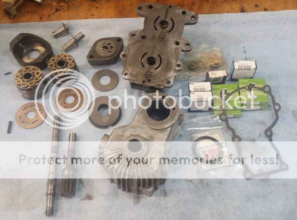
So that's where I am as of today. Here's the "kit" all laid out, minus the check & relief valves. Clean as a whistle and begging to go back together.
 photo hyparts.jpg
 
I posted this in the rebuild thread too. I kinda forgot I started this one it was so long ago I started this mess.
I have lapped all the appropriate surfaces and stoned all the flat sealing surfaces, washed thoroughly in solvent, dried with a blast of air and coated everything with an aerosol lubricant to preserve it until it gets filled up. Then put it all in ziplocs until I can put them back together.
The check and relief valves have been gone through, but I've decided that I have four check valves which are still working fine so I'm not going to completely rebuild them. I don't think that will bite me in the butt, at least any time soon. They are relatively easy to access so if they need attention in the future, I'll address that then. One of the relief valve seats was eroded away. I'm suspecting cavitation. I chamfered the seat until it was to good material in the center again, then made a lap the same angle as the poppet and lapped it back to good condition. All I should need to do is shim it, but if need be I'll wind a longer new spring to replace it. One of the relief valve springs looks like it has been "spring" and I may have to make a replacement anyway. I'm trying to figure out an easy way to maybe power it with a big drill press or something to check the pressure and adjust the relief valve to specification before I mount it in the machine. I haven't thought of a good way yet, but maybe something will come to mind.
The control yoke and input shafts had slightly worn sealing surfaces, but it only took spinning it in the lathe and carefully polishing back to smooth again. They are only about a half thou smaller than original - that's good.
So that's where I am as of today. Here's the "kit" all laid out, minus the check & relief valves. Clean as a whistle and begging to go back together.
Looks good, putting parts in bags with lubricant is a good idea. I do the same when parts aren't going to be used straight away, you don't want to put them away dry and have them rust from your finger prints.
I have drive motors that i rebuilt years ago, when i assembled them i used lots of oil and put them in a bag when completed to keep the moisture out.
I didn't think of it as a standard tip, but now that you mention it I think I may do that more in the future. After I lapped things in three phases, it just got placed in a box until I could get to it next time. But the box was behind a lathe and next to a blasting cabinet, both of which got used a few times while stored there and all kinds of debris got sprinkled over it all. Washing it all off thoroughly was a must and I just wanted it protected "for sure" between now and assembly day.
All parts for both hydros are now staged for assembly. All I need are the pins I ordered from McMaster Carr so I can put it together with new - a little insurance. They are usually fast shippers so I think I'll have these together before the weekend.
My only wrinkle is setting the charge relief valve, or at lest putting the gauge on them to test pressures. I will probably think of a way to do that. Prolly just need to gather up a hose, drain pan and a jug o' fluid and rig it up. When I try to visualize how to do this in my head, it always looks kind of like a treehouse, hehe. But if a treehouse will work, a treehouse it is.
I have a tragedy strategy for setting the charge pump bypass pressure before installing them. I just need to put the hydros together first, then I think it would be easy to figure out a way to clamp it to the table of the big drill press at work. I can simply hook up a hose for the fluid supply and a drip pan to catch it as it exits - there's no return hose since it's supposed to flow through it and into the gearbox before going back to the tank.
I very often handicap myself trying to think stuff to death first instead of just diving in and dealing with things as they come. As a machinist, you pretty much have to think the whole project through so you don't get bit in the butt near the end and that's a habit of mine even when it's not necessary, or worse at times when it's not a good idea anymore. Anyway, the drill press will supply rotation to the input shaft with as much as 7hp which should be plenty to check the pressure.
I took care of something today in an effort to avoid an afterthought. Cleaned all the bolts and painted the heads:
 photo Bolts.jpg
I should have the pins in the mail tomorrow so I can probably put these together tomorrow night. Still need to get some fluid to soak everything as I'm putting it back together. Otherwise, I think I'm pretty well all set.
 
I have a tragedy strategy for setting the charge pump bypass pressure before installing them. I just need to put the hydros together first, then I think it would be easy to figure out a way to clamp it to the table of the big drill press at work. I can simply hook up a hose for the fluid supply and a drip pan to catch it as it exits - there's no return hose since it's supposed to flow through it and into the gearbox before going back to the tank.
I very often handicap myself trying to think stuff to death first instead of just diving in and dealing with things as they come. As a machinist, you pretty much have to think the whole project through so you don't get bit in the butt near the end and that's a habit of mine even when it's not necessary, or worse at times when it's not a good idea anymore. Anyway, the drill press will supply rotation to the input shaft with as much as 7hp which should be plenty to check the pressure.
I took care of something today in an effort to avoid an afterthought. Cleaned all the bolts and painted the heads:

I should have the pins in the mail tomorrow so I can probably put these together tomorrow night. Still need to get some fluid to soak everything as I'm putting it back together. Otherwise, I think I'm pretty well all set.
I was hoping I could get both hydros together tonight, but I had to make a few tools. And it's surprising how dirty your tools get over time, so I also kept having to wash tools off as I went to lessen the chance of gritting up the innards just for trying to put things together. But I completed one anyway. At least the tools are already clean and the custom stuff is made already so #2 will go faster.
Here's the stuff all laid out:
 photo H Parts1.jpg
And after a bunch of slathering everything as I went with hydraulic oil and some wrenching and pressing, here's what came out the other end:
 photo H Assy1.jpg
The press tools for various bearings are in the lower left. The black ring is one of the gaskets I made earlier today. I made an extra too just in case.
So a little more progress. They'll get a coat of paint before they go in. I feel pretty confident that it's all in good shape and assembled properly. I tell you what. I'm going to have a beer or few after these hydros are finished. They've been on my mind for months now. I know it's stupid for these eimple little things to take so long, but that's just the way things have been going for me the past year or so.
 
I was hoping I could get both hydros together tonight, but I had to make a few tools. And it's surprising how dirty your tools get over time, so I also kept having to wash tools off as I went to lessen the chance of gritting up the innards just for trying to put things together. But I completed one anyway. At least the tools are already clean and the custom stuff is made already so #2 will go faster.
Here's the stuff all laid out:

And after a bunch of slathering everything as I went with hydraulic oil and some wrenching and pressing, here's what came out the other end:

The press tools for various bearings are in the lower left. The black ring is one of the gaskets I made earlier today. I made an extra too just in case.
So a little more progress. They'll get a coat of paint before they go in. I feel pretty confident that it's all in good shape and assembled properly. I tell you what. I'm going to have a beer or few after these hydros are finished. They've been on my mind for months now. I know it's stupid for these eimple little things to take so long, but that's just the way things have been going for me the past year or so.
Taking your time is a good thing, you don't want to mess them up.
If you have fiddly parts, use a bit of grease to hold them in place too. Especially springs and metal balls. Grease holds them in palce.
Looking good, and i like the fact you are keeping things extra clean. For things like this, you don't want any rubbish getting in.
i just thought i would bump this up. i recently had a hydro static drive falure on my gehl 2500 long story short, failed hose between the filter and the hydrostatic drive. slammed a new hose in without taping up the ends being sloppy and in a hurry when i fished it threw witch in turn got a small piece of dirt in the hose witch broke the sheer pin in the charge pump took a chip out of the charge pump housing and gacked the shaft. once i found this thread and found out it was a sunstrand model 15 type u it made getting information much easier ended up buying a good used drive from a john deer. old drive is taken apart, new one is sitting in a unopened box awaiting me to find a few hours of time. plan is to pull the new pump apart inspect, swap the swash plates, slam it back together plug the implement ports, pull the charge pressure relief valve out put in in place of the implement valve pull the guts out of the implement valve and just use the cap install it back in the open hole, slam it in and all should be good. or so goes the plan.
 
Back
Top