Need pictures of drive control to help reassemble

Help Support SkidSteer Forum:

rowow

New member
Joined
Apr 19, 2023
Messages
3
Hello I've been working on putting back this new Holland l555 skid steer the past 4 months and am at my final things to do. The biggest issue I'm having is figuring out how and where the spring return for the drive controls fit. (Bought from previous owner already taken apart)

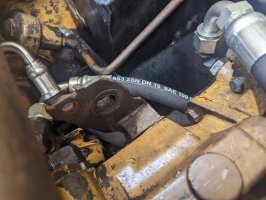
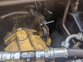
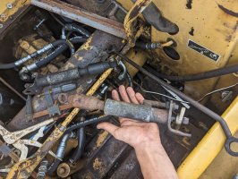
I'm looking for pictures of the brackets and everything else associated to the drive control. As many pictures or a video would be greatly appreciated!
 

Attachments

  • PXL_20230419_195450050.jpg
    PXL_20230419_195450050.jpg
    414.6 KB · Views: 75
  • PXL_20230419_195446007.jpg
    PXL_20230419_195446007.jpg
    445.9 KB · Views: 65
  • PXL_20230419_195439382.jpg
    PXL_20230419_195439382.jpg
    572.2 KB · Views: 72
OP
OP
R

rowow

New member
Joined
Apr 19, 2023
Messages
3
Try this link and select the correct "diagrams" -Stef

Hello Im aware of this website and used it alot but it doesnt help in figuring out where the brackets attach to the actual frame of the machine and the way they are positioned compared to the hydraulic hoses.
 

Stef

Member
Joined
Oct 6, 2021
Messages
17
Hopefully someone can provide you the pictures you desire however, in the absence of those, you could use diagram 099 to help figure it out.

The control arms 5 and 15 each connect from the short brackets at the bottom of each control handle to each of the control valves on each side of the the transmission. If installed correctly, moving each of the control handles functionally moves the corresponding transmission control valve. At this point, the control handles move easily forward and back with no "dampening" force felt.

The second part is installing the dampeners on each side, one forward facing and one rearward. From your photos, it appears your dampers are already assembled (2x drawing assemblies 8-13). One end of each damper connects to the transmission control valve bracket, and the other end to a bracket attached to the frame. Holding the dampers in place should help determine where that location is.

I understand the photos would be much more helpful, but in their absence you do not need to be dead in the water. -Stef


Temp.jpg
 
Last edited:
OP
OP
R

rowow

New member
Joined
Apr 19, 2023
Messages
3
Hopefully someone can provide you the pictures you desire however, in the absence of those, you could use diagram 099 to help figure it out.

The control arms 5 and 15 each connect from the short brackets at the bottom of each control handle to each of the control valves on each side of the the transmission. If installed correctly, moving each of the control handles functionally moves the corresponding transmission control valve. At this point, the control handles move easily forward and back with no "dampening" force felt.

The second part is installing the dampeners on each side, one forward facing and one rearward. From your photos, it appears your dampers are already assembled (2x drawing assemblies 8-13). One end of each damper connects to the transmission control valve bracket, and the other end to a bracket attached to the frame. Holding the dampers in place should help determine where that location is.

I understand the photos would be much more helpful, but in their absence you do not need to be dead in the water. -Stef


View attachment 3579
Hello thank you for trying to help and ive gotten everythng you described assembled and figured. Currently my last puzzle is trying to figure out where 22 or 19 attaches to the skid steer itself. I was able to find the left side damper attaches to a bracket sticking out from the hydraulic mount on the front if anyone else reading this in the future is having issues.
 

Ivan

Well-known member
Joined
Jan 14, 2011
Messages
215
Hello thank you for trying to help and ive gotten everythng you described assembled and figured. Currently my last puzzle is trying to figure out where 22 or 19 attaches to the skid steer itself. I was able to find the left side damper attaches to a bracket sticking out from the hydraulic mount on the front if anyone else reading this in the future is having issues.
they go into bracke t that is bolted to the top of where the tran mounts to the engine
 

Latest posts

Top