


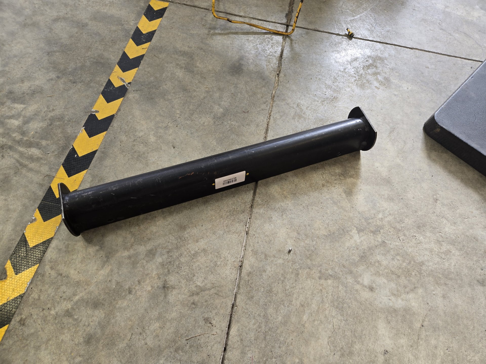
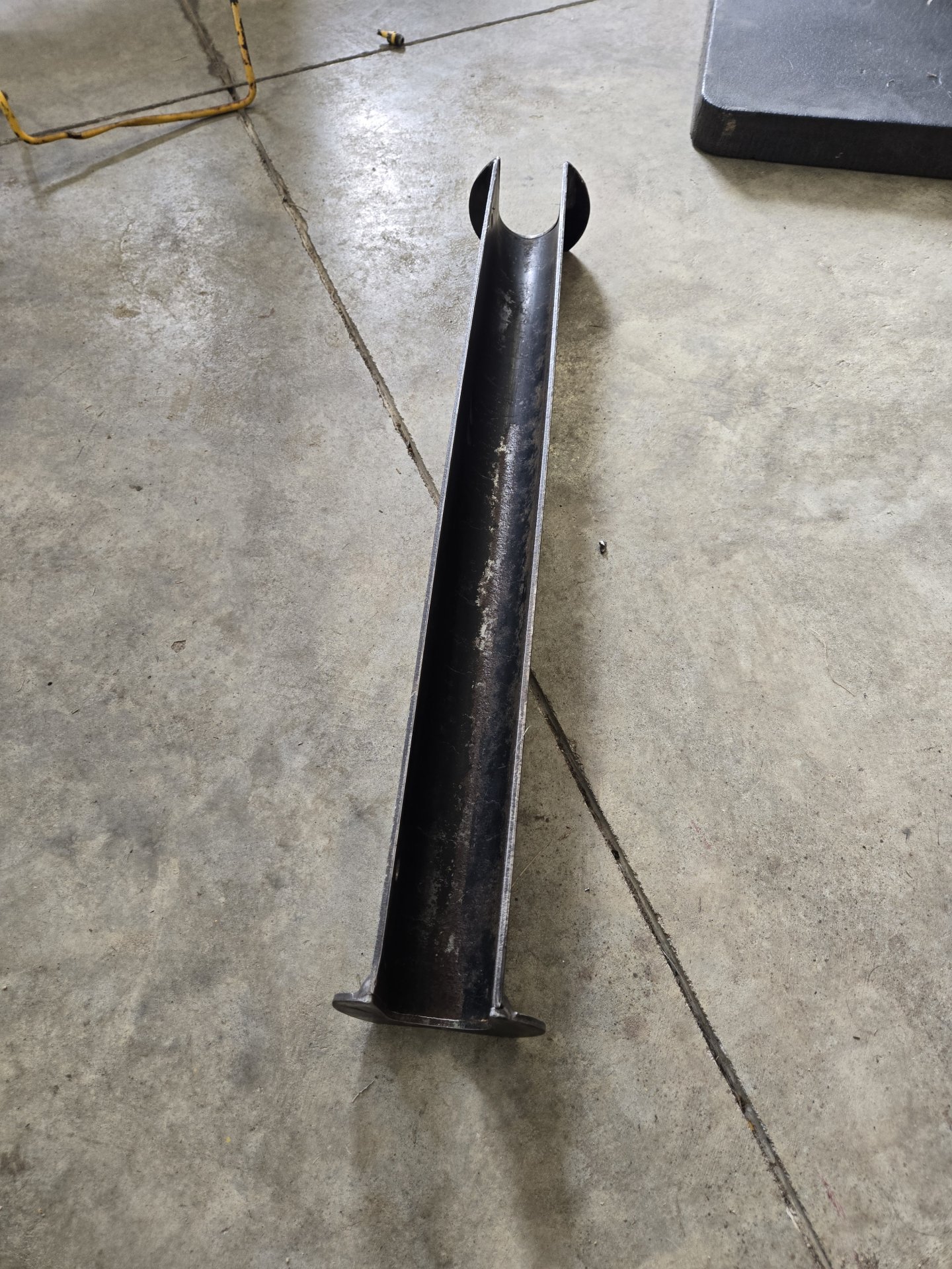
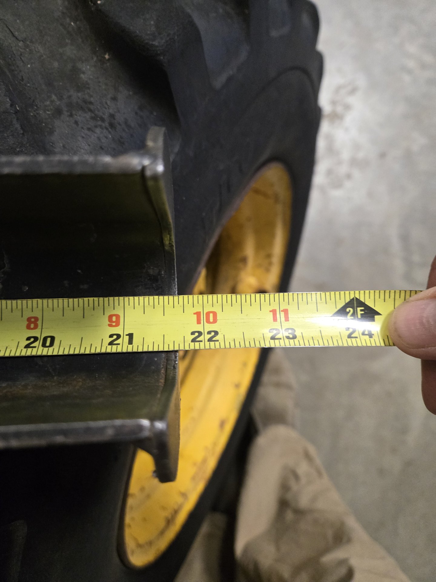
Come to think of it, they probably want to avoid liability for not warning of a over pressured torque converter positioned directly between operators legs .Here's a couple of photos of the prepped engine area. New rubbers for the engine mount and the parts 1700 had really nice radiator ones, so I put those on. I measured the old engine rubbers best I could as they were a disaster, beyond recognition.
View attachment 10631 View attachment 10632
I'm trying to pull the fourth function lines from the parts machine. They were not on this machine when I bought it. Those will go on and then I think it's ready for an engine. Oh, and I'm still working on making hydraulic hoses. The neighbor farmer has a hydraulic hose business as a side hustle so I'm trading work for hoses. I also now have the steel to make a belly pan. I just can't see running this without one. I might wait until I can get the machine on the lift/hoist but the No. 7 sheet steel is dang heavy.
Al Jones
Brookings, SD

You are using an out of date browser. It may not display this or other websites correctly.
You should upgrade or use an alternative browser.
You should upgrade or use an alternative browser.
Mustang 1700 Reset
- Thread starter jonesallu
- Start date
OP
OP

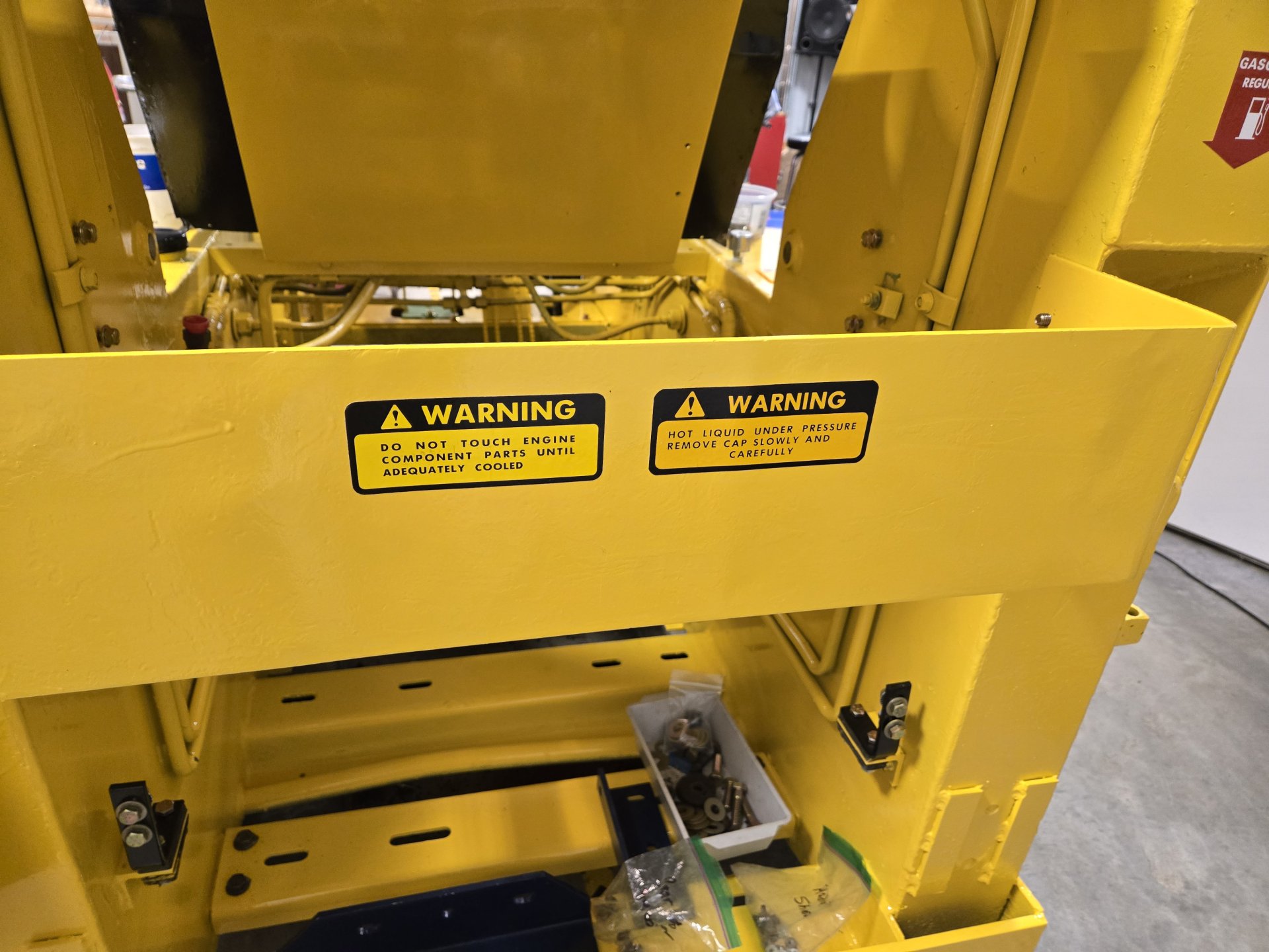
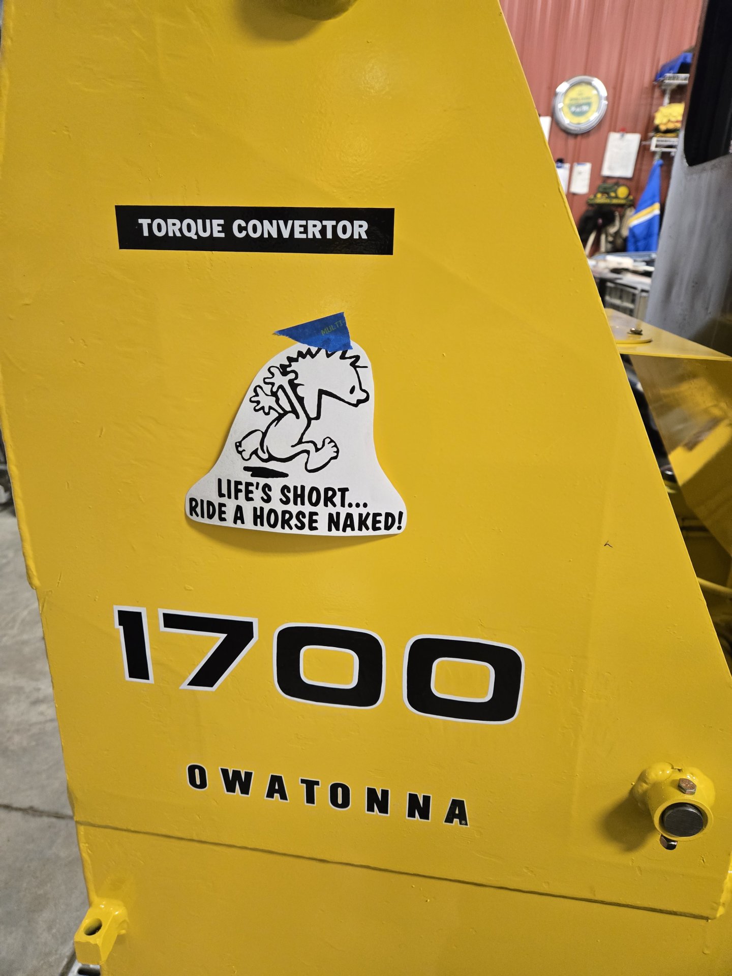
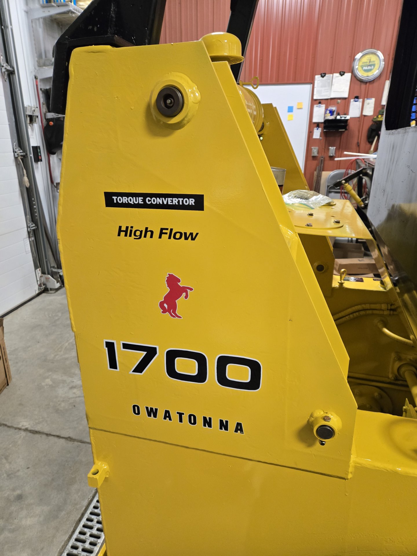
Decals. Started pasting some on as a motivation. I was getting a little burned out but these got me going again. Comments on top.
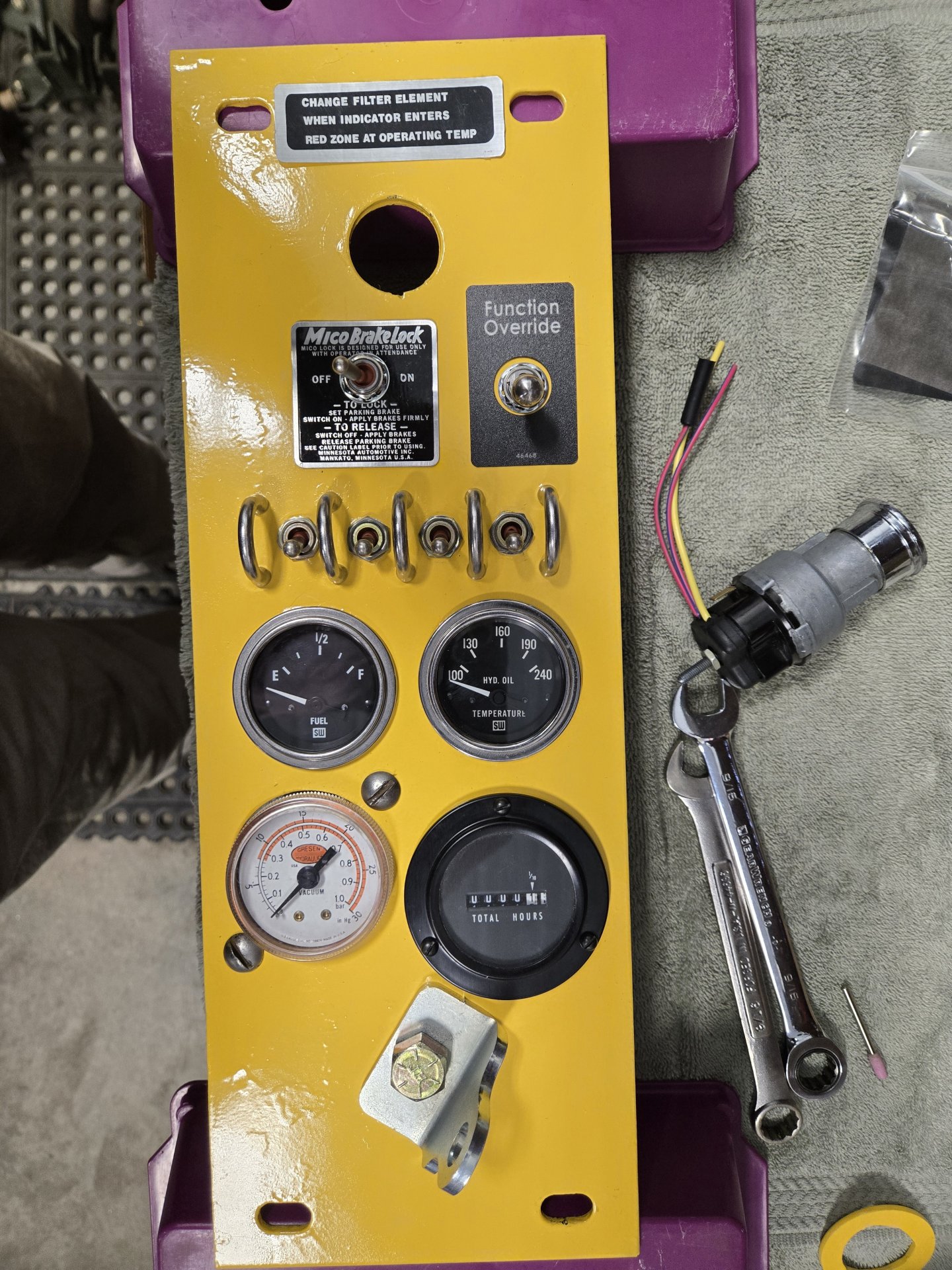
Filter element, brake lock plate and master safety override on the gauge/switch panel.
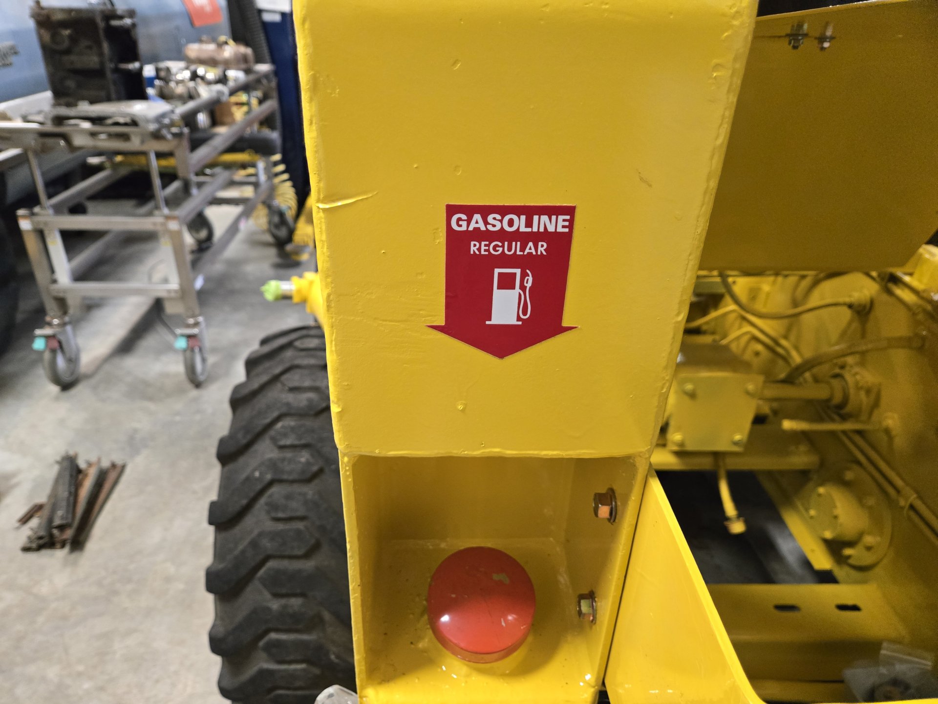
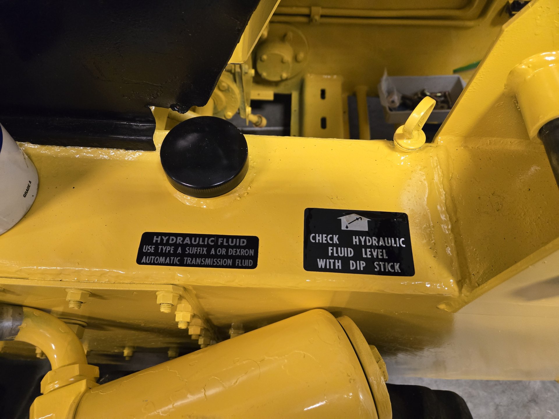
Note what this one says near the fill cap. Refer back to the conversation on proper fluids. ???
Wife vetoed this. So I put a red pony on for her.
Filter element, brake lock plate and master safety override on the gauge/switch panel.
Note what this one says near the fill cap. Refer back to the conversation on proper fluids. ???
Wife vetoed this. So I put a red pony on for her.
OP
OP
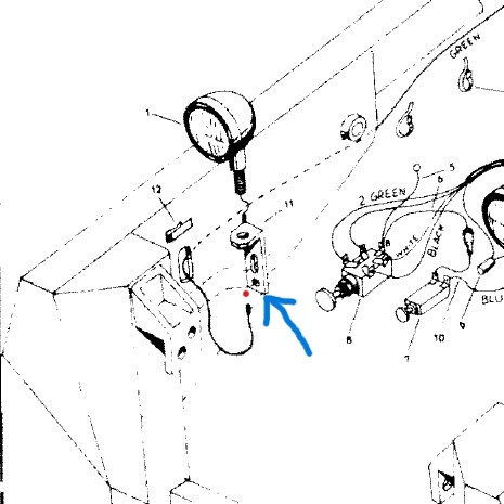
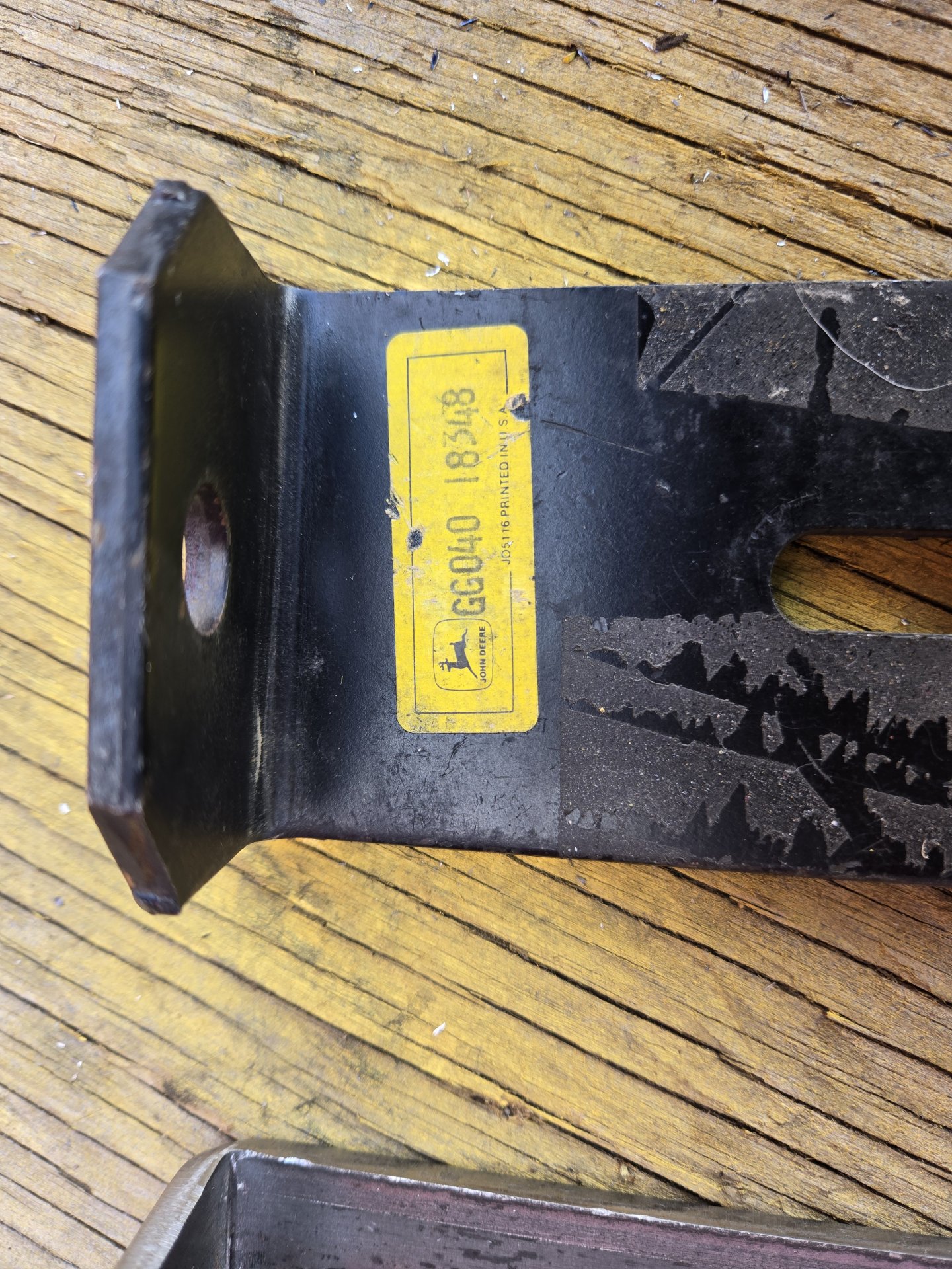
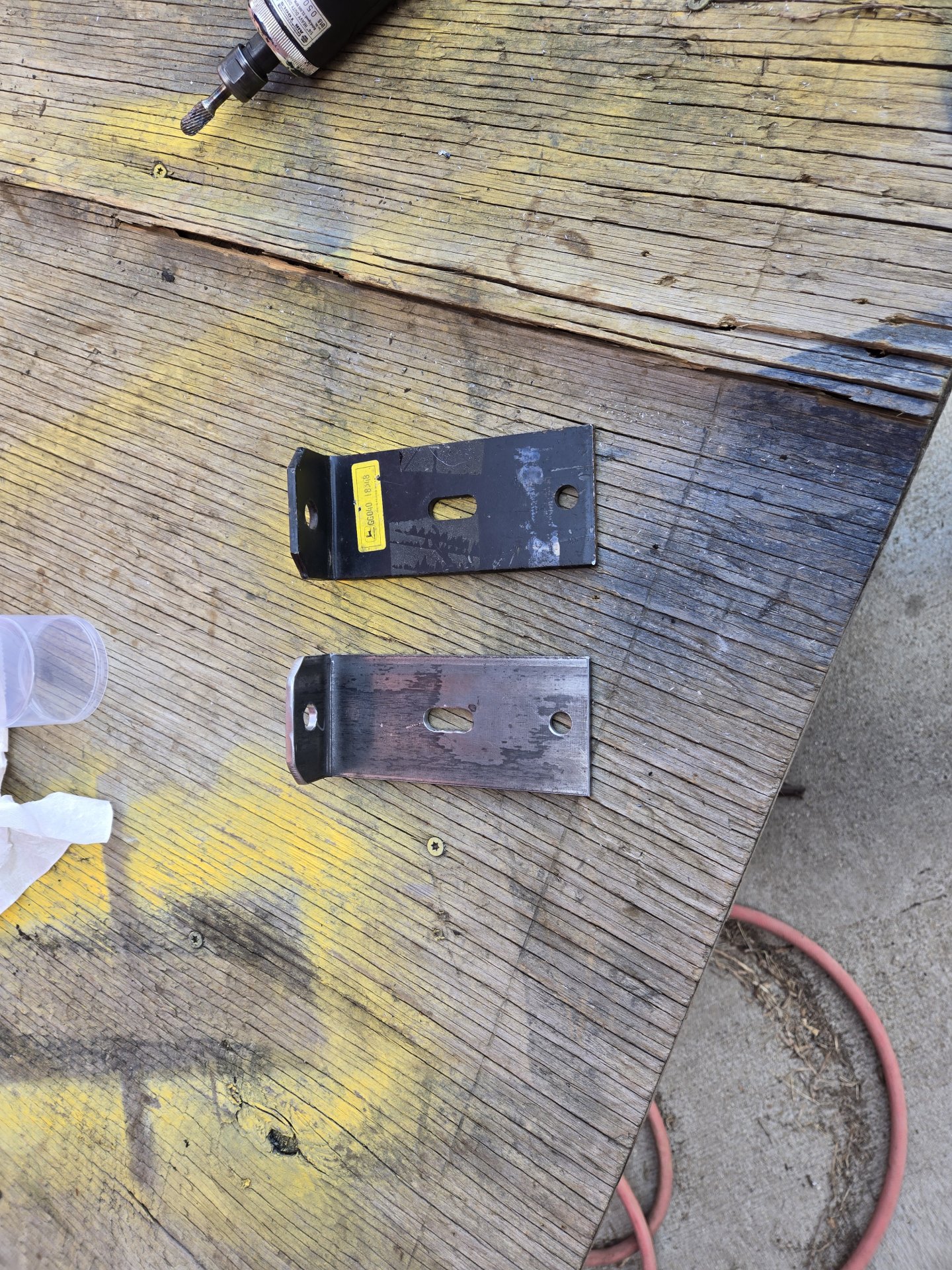
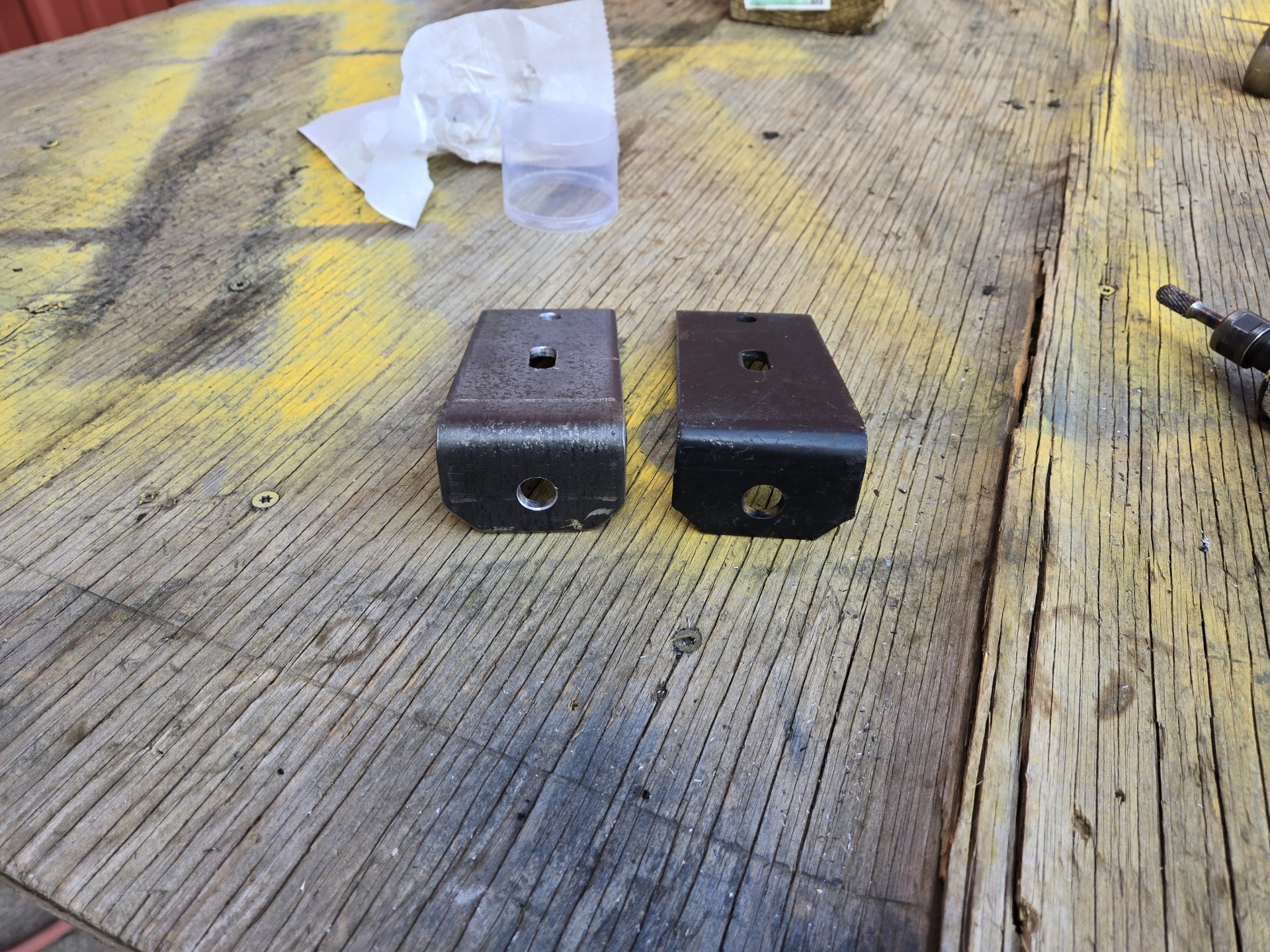
Found an NOS light housing bracket that goes on the boom. It was part of the "light kit" that's shown in the parts book. I fabricated a copy for the other side. I have a pair of round LED units I'll put on.
Al Jones
OMC Mustang 1700
Al Jones
OMC Mustang 1700
OP
OP
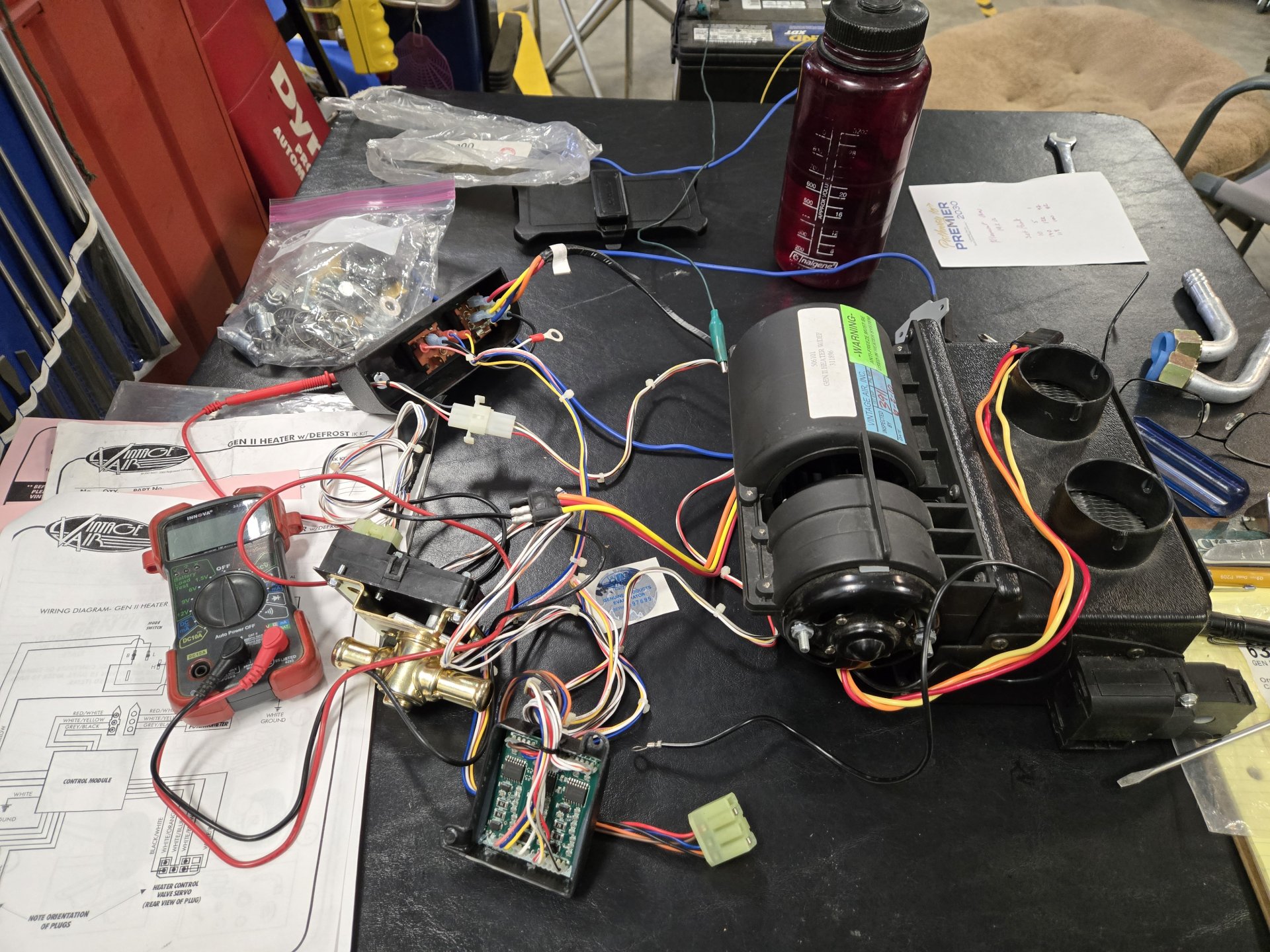
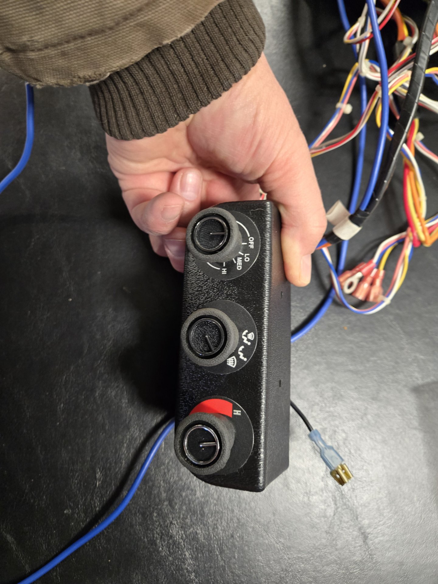
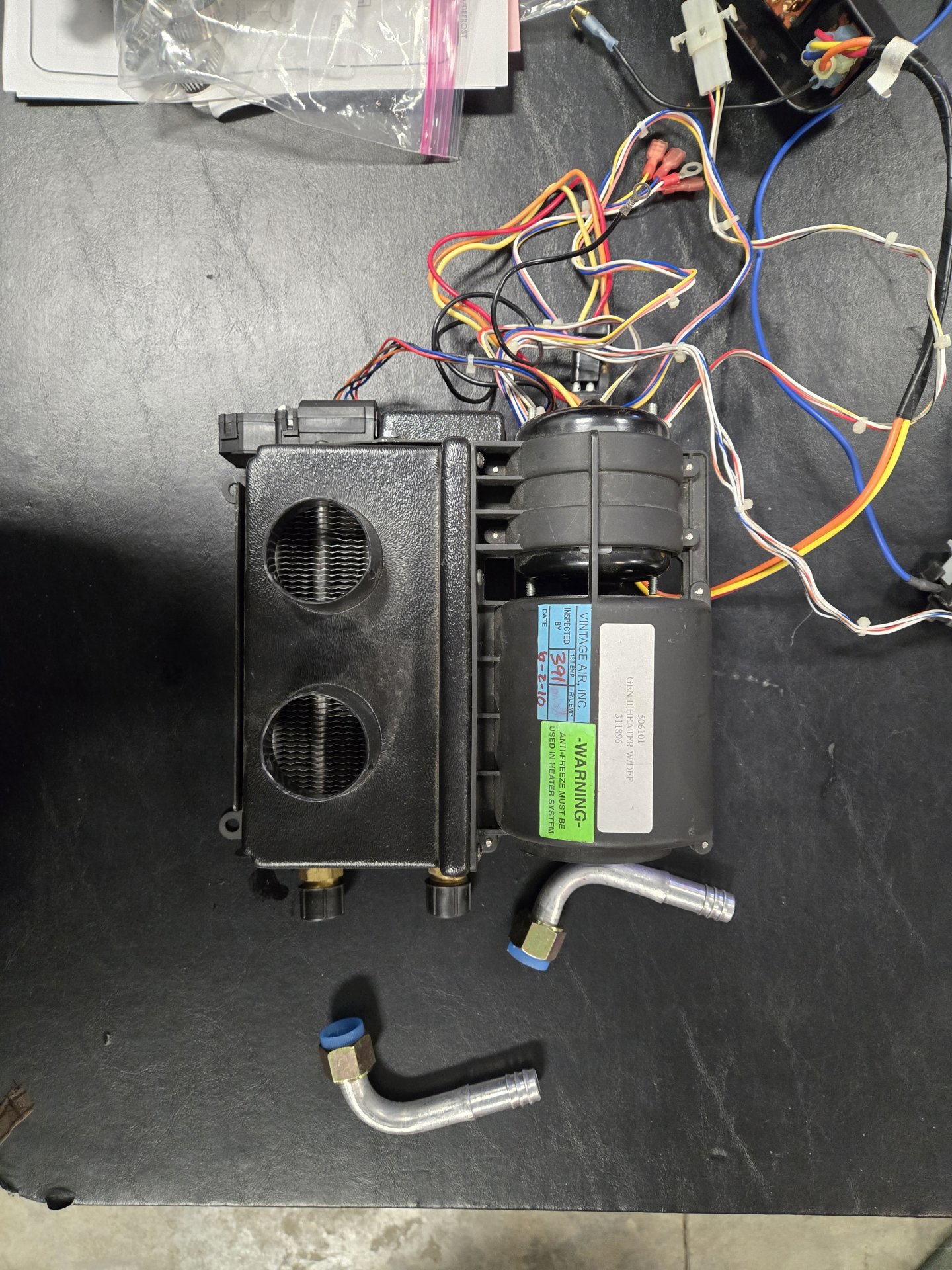
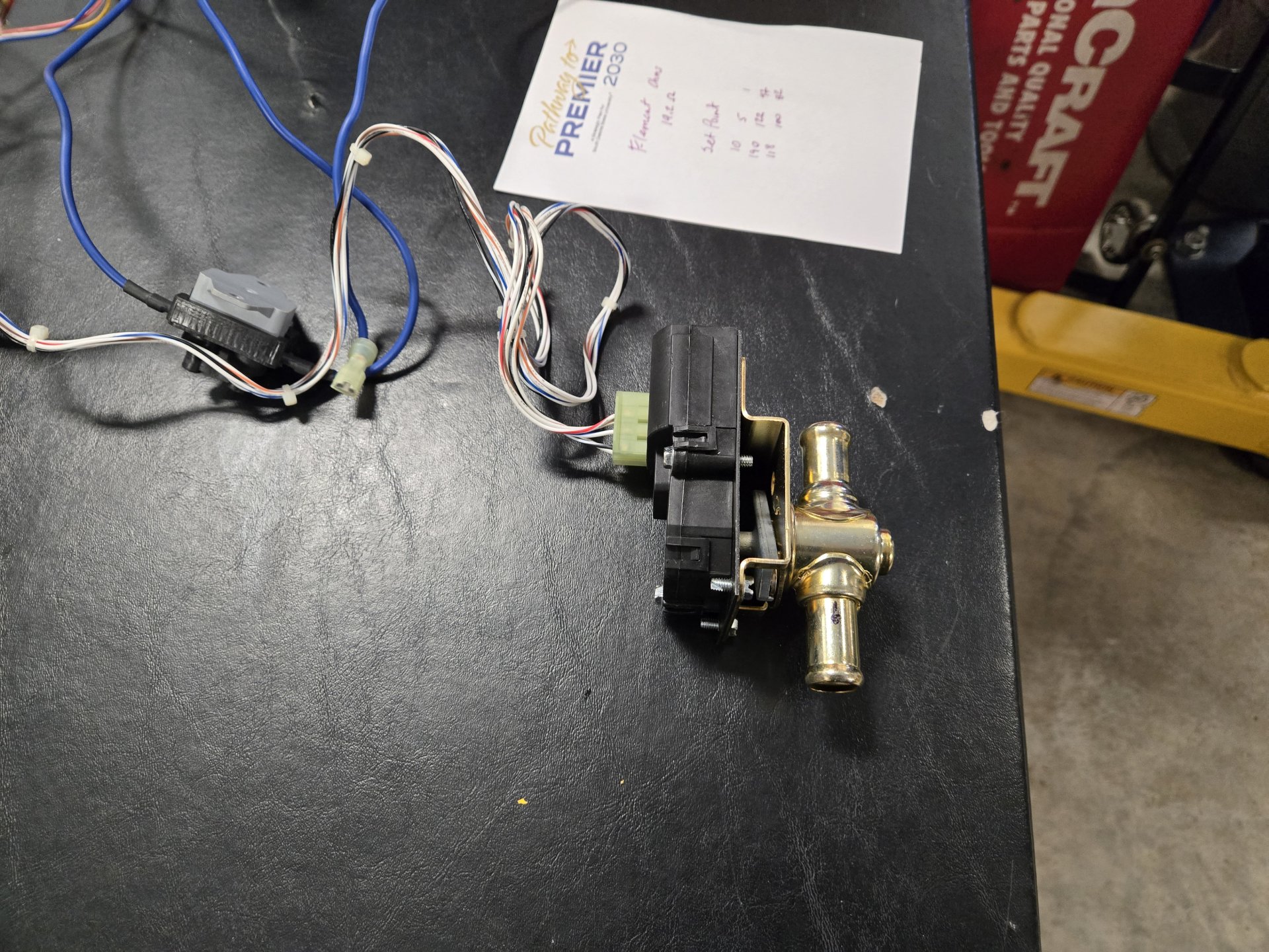
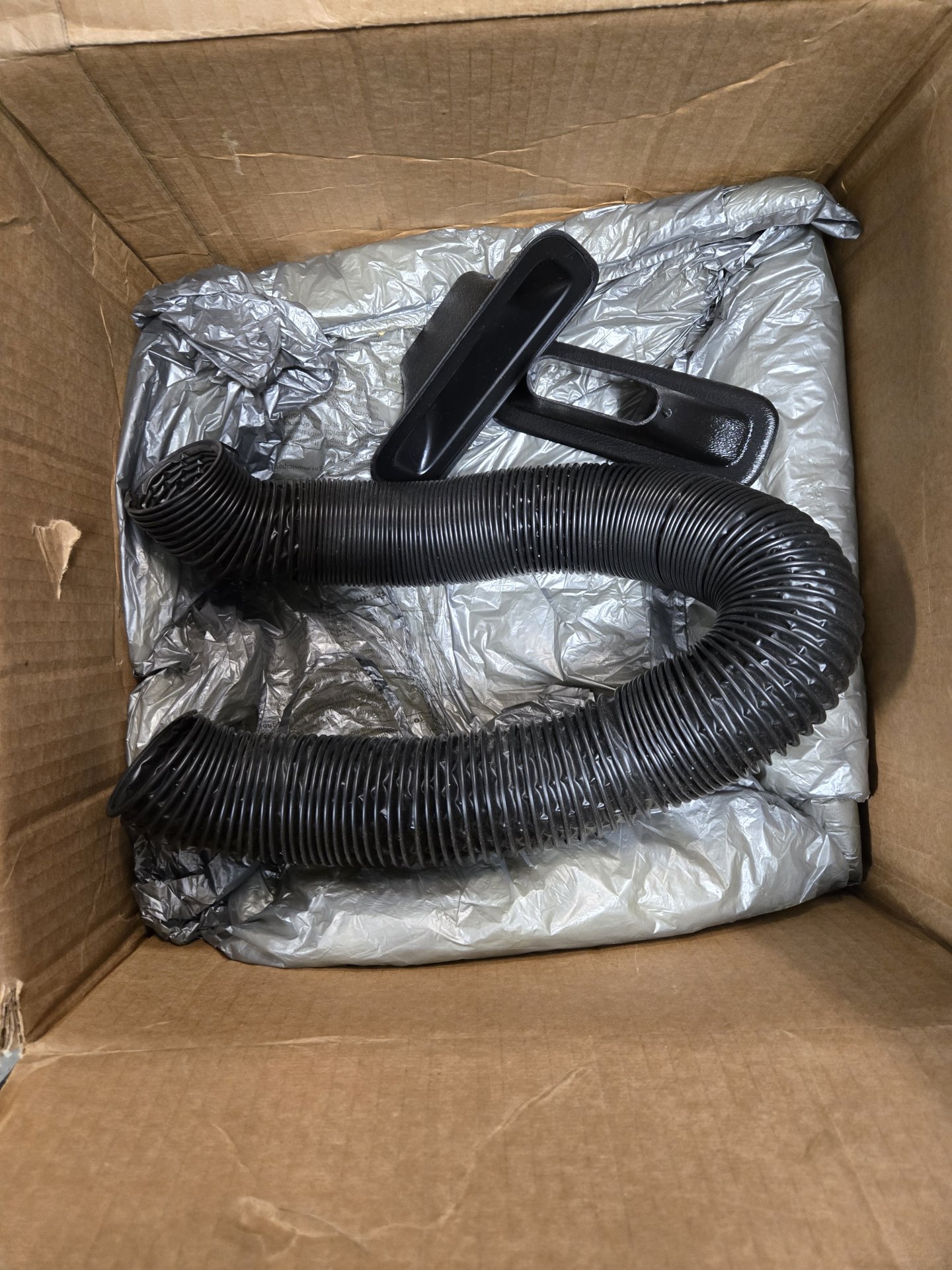
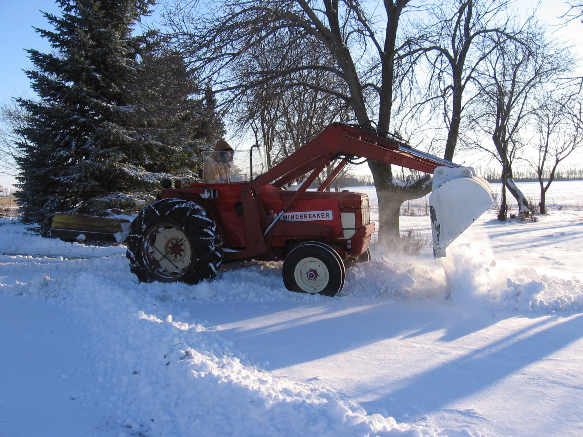
THIS is the reason for this entire project. I swear I'm the last person in South Dakota that still clears snow in an open cab tractor. I hope this was my last year doing that. Clearing snow at 20 below zero is not nice on my old bones. This may look like a mess but It's a dandy setup that is **very compact**. Note: no cables for heat/defrost blend or amount of antifreeze flow. Both are controlled by servos. Mounting the main unit might not be optimal, but I'll deal with it. Vintage Air wants a bundle for the kit so I waited on ePay until I could snag an open box one for $100. It moves air! The Palm Cab steel framing will work very well for helping to route the defrost ducts to the front door.
Al Jones
Still clearing snow in an open cab tractor
Al Jones
Still clearing snow in an open cab tractor
OP
OP
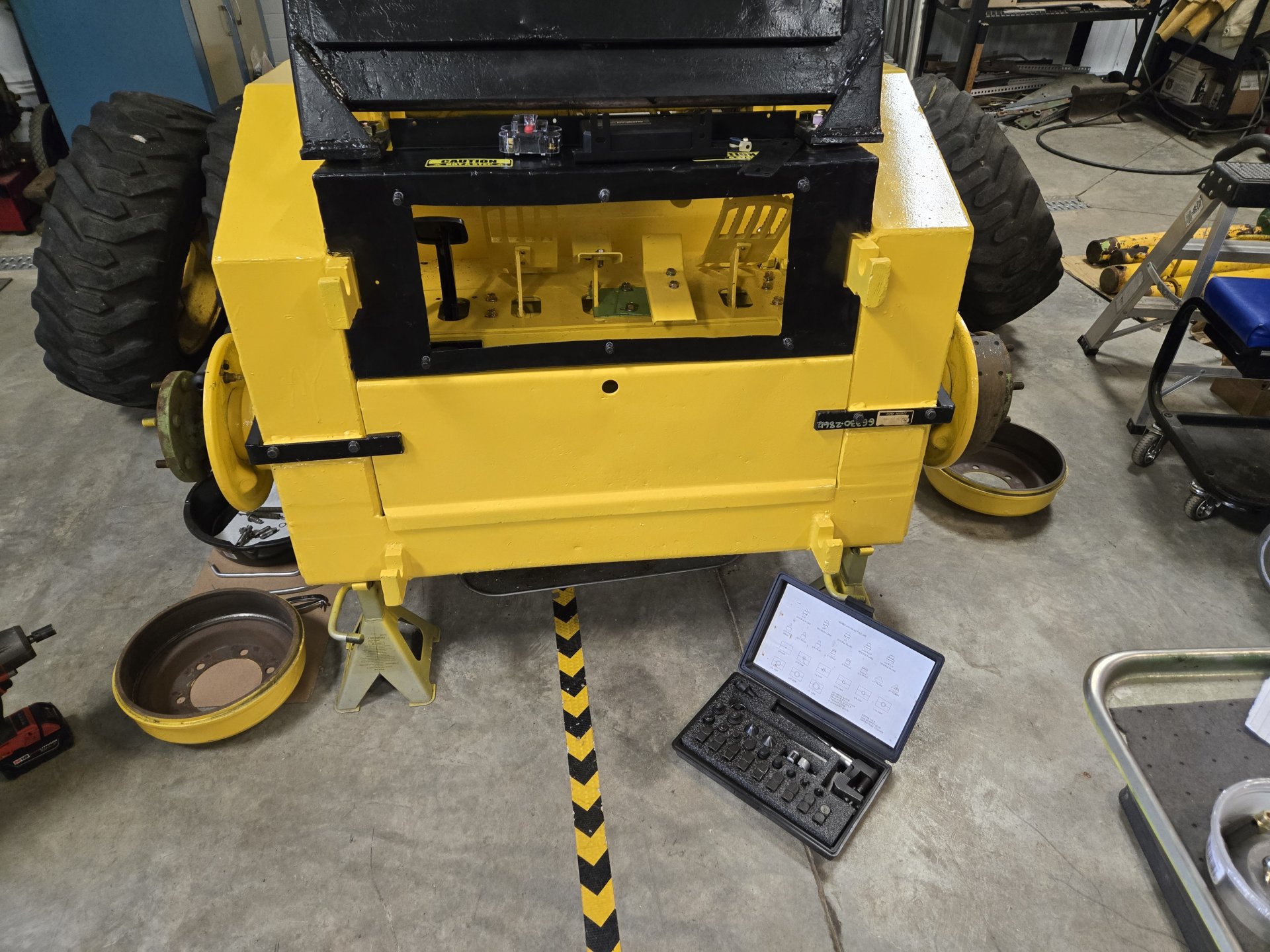
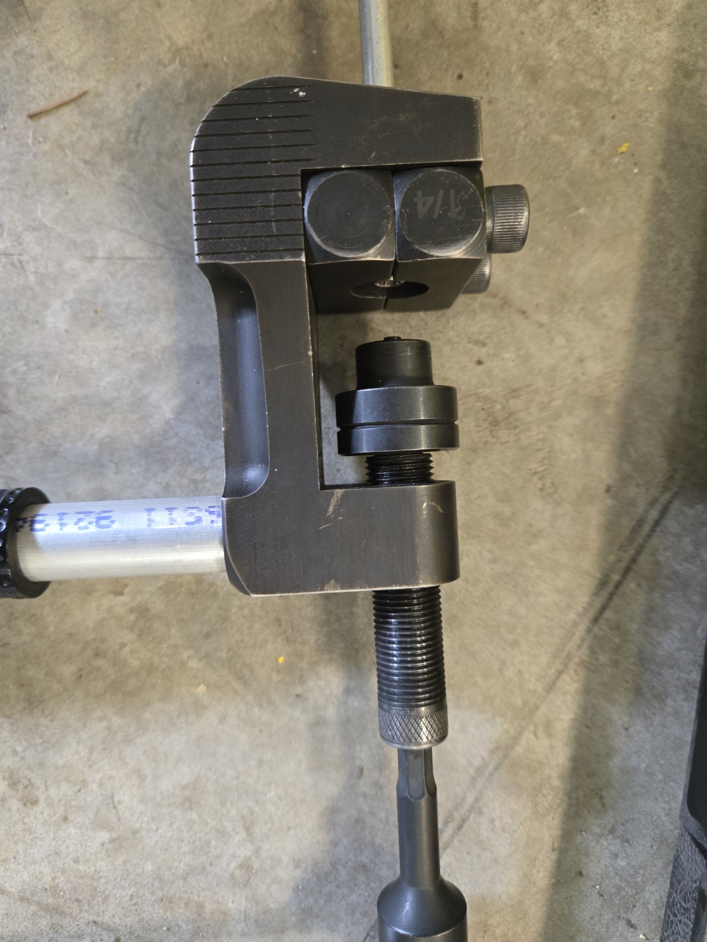
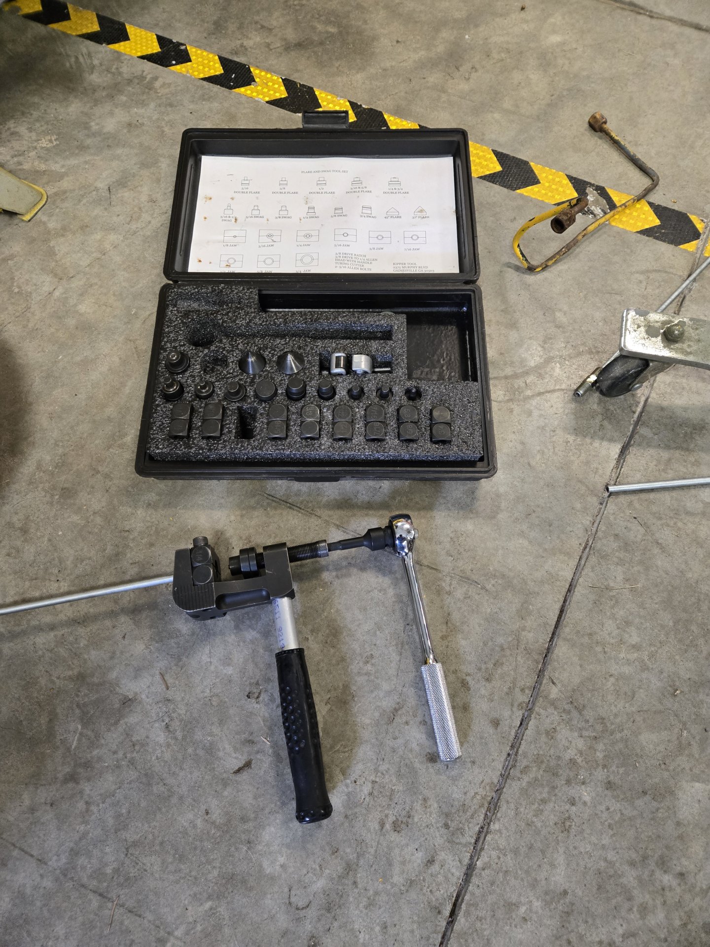
I finalized the brake lines. I used armored brake line from the wheel cylinder to the brake line guard, and then used regular line elsewhere. It's interesting that OMC used inverted flare from the wheel cylinder to the guard, and then used JIC after that to the master. I used all inverted flare to make life easier. Photos follow.
Bending lines. Note that the 8" long wheel cylinder line is 3/16" and then transitions to 1/4". I used a 3/1" to 1/4" union adapter to hook the two together.
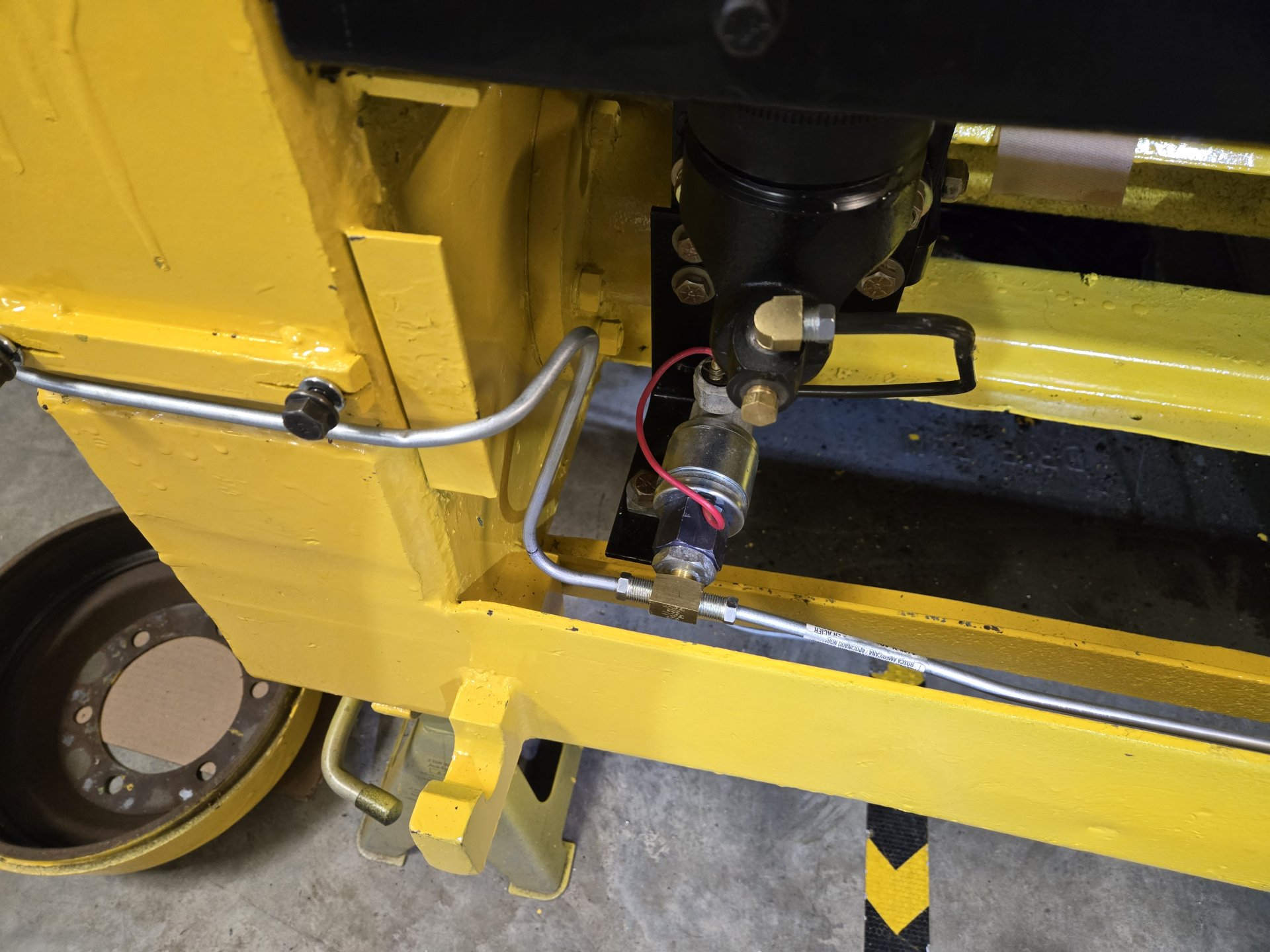
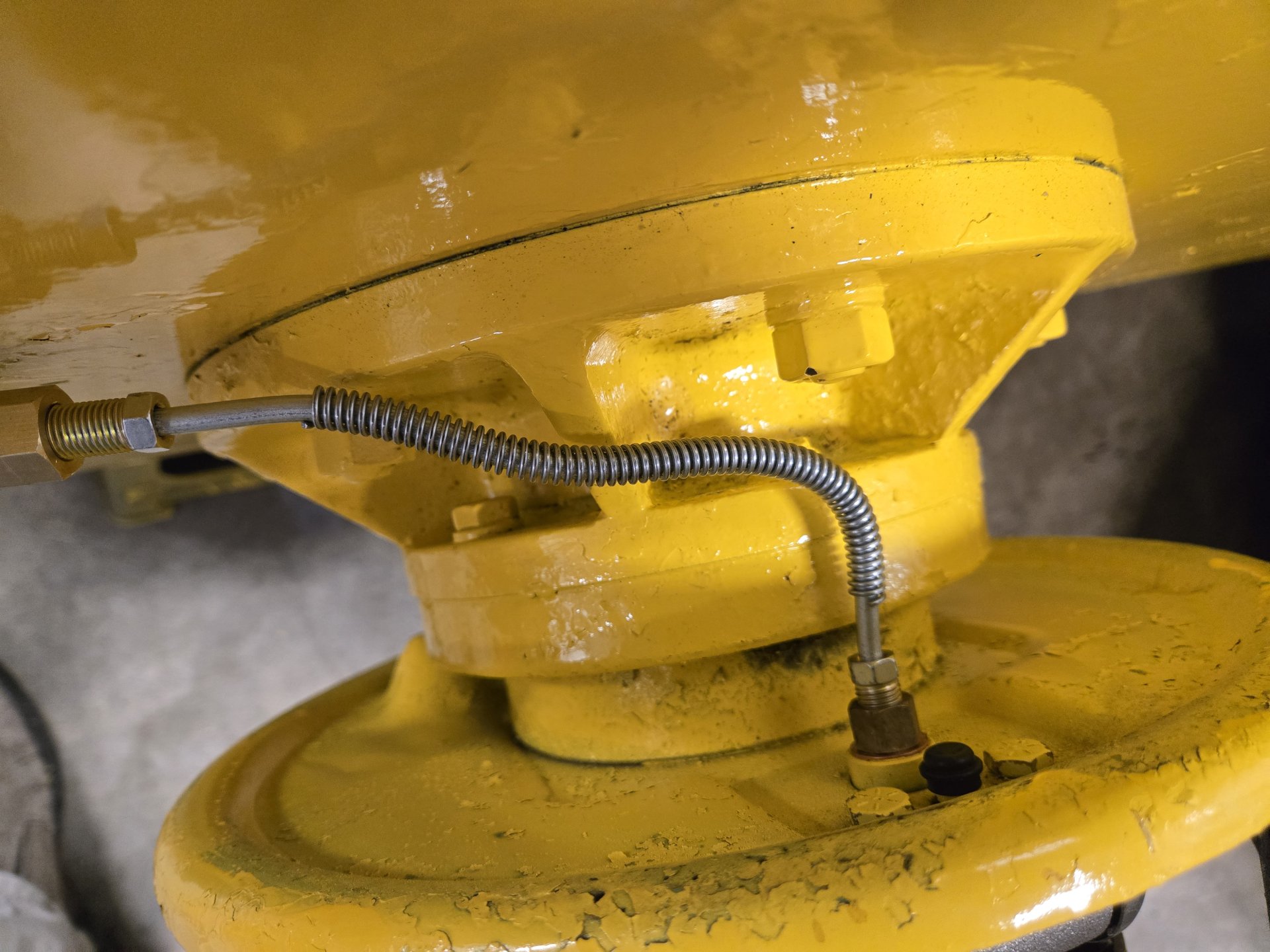
Left NOS guard and right guard I fabricated.
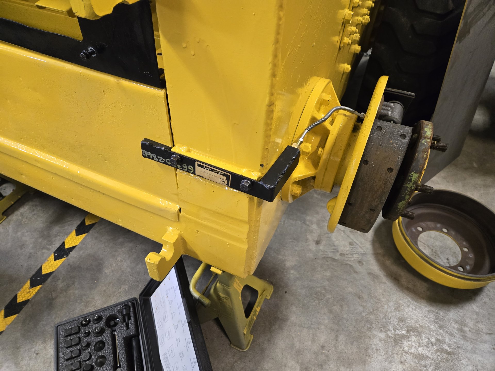
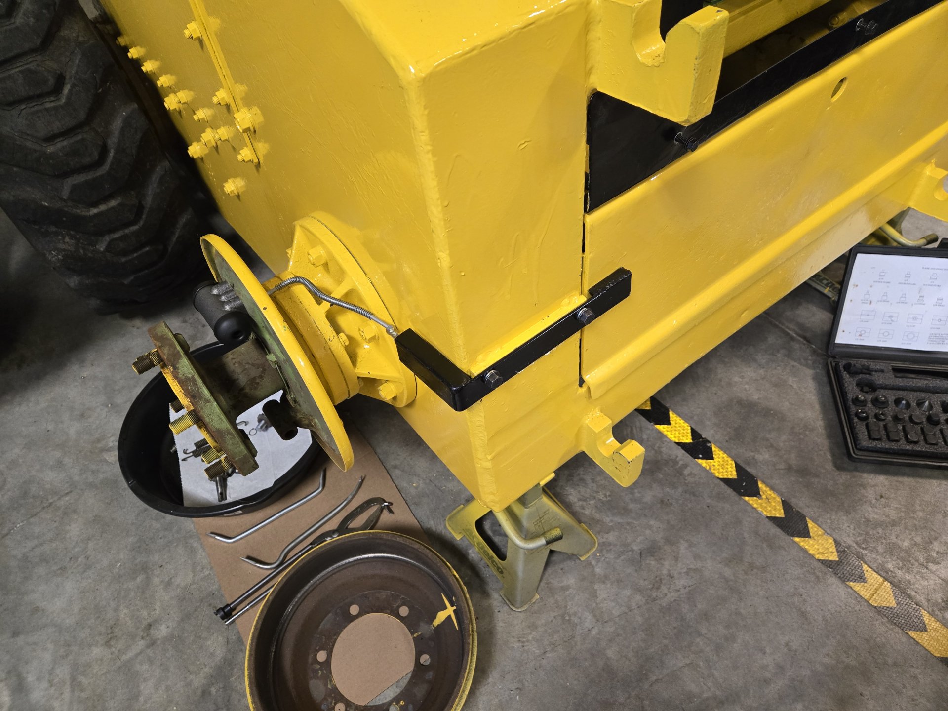
Final product
Tooling for inverted flare.
Cheers,
Al Jones
Bending lines. Note that the 8" long wheel cylinder line is 3/16" and then transitions to 1/4". I used a 3/1" to 1/4" union adapter to hook the two together.
Left NOS guard and right guard I fabricated.
Final product
Tooling for inverted flare.
Cheers,
Al Jones
OP
OP
The NOS torque convertor came in. It's a spendy unit. Looks like the fan on the old TC fell off. I can see the spot welds where it was attached. If that fell off when it was running I suspect it made a heck of a racket. I see there are also ones on ePay for sale.
![20260312_173211[1].jpg](https://cdn.skidsteerforum.com/a/7734-d1cf04dd13b917594840fa2a09170e6e/20260312_173211%5B1%5D.jpg "20260312_173211[1].jpg")


![Pampers Sensitive Baby Wipes, Clinically Proven, Fragrance Free, Unscented, Water Based, Hypoallergenic, Multi-Use, Hand Wipes 336 Wipes Total (6X Flip-Top Packs) [Packaging May Vary]](https://m.media-amazon.com/images/I/41KLBHu9CAL._SL500_.jpg)






As an Amazon Associate we earn from qualifying purchases. Product prices and availability are accurate as of the date/time indicated and are subject to change.
OP
OP
Progress. Boom locks, electrical and more brakes.
I found an NOS boom lock and will either duplicate it for the other side or beg if someone has one for sale they don't want. I have a nice boom lock setup off a Case skid steer that I was intending to use until I found this. Anyone have one to sell?
Here's the status of the electrical.
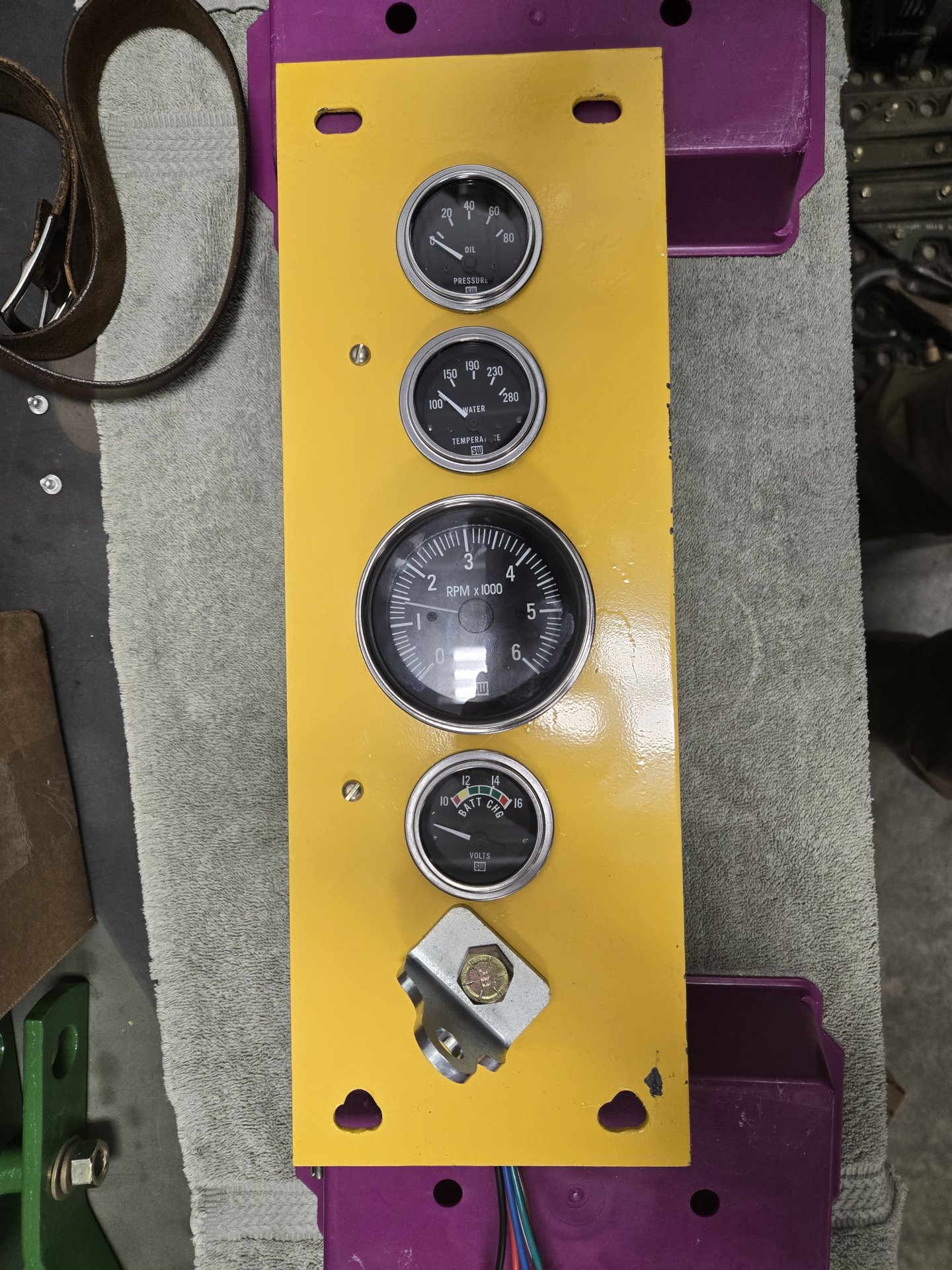
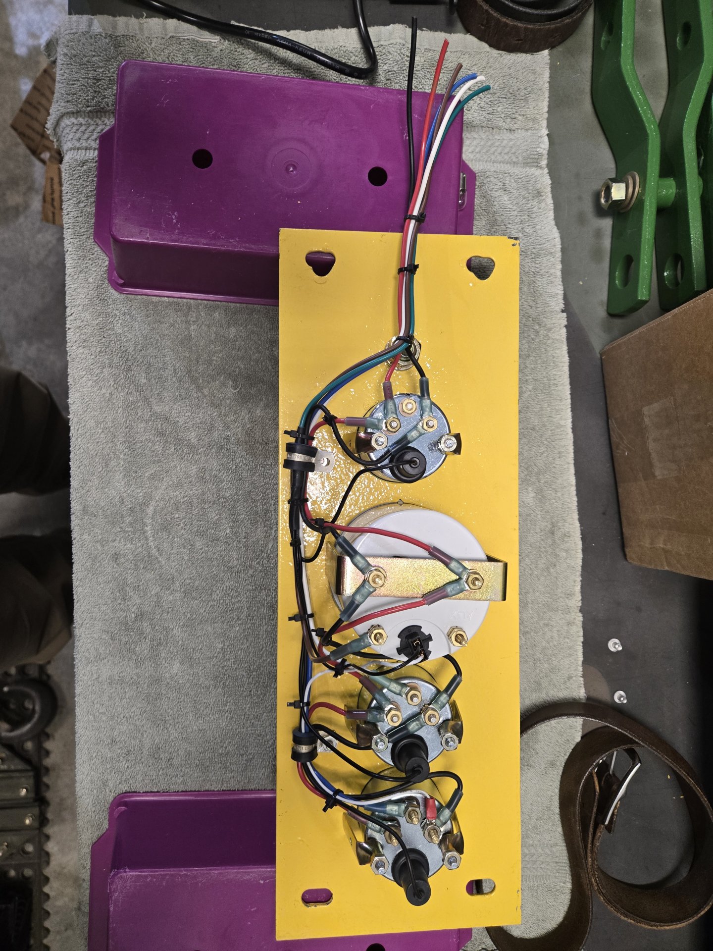
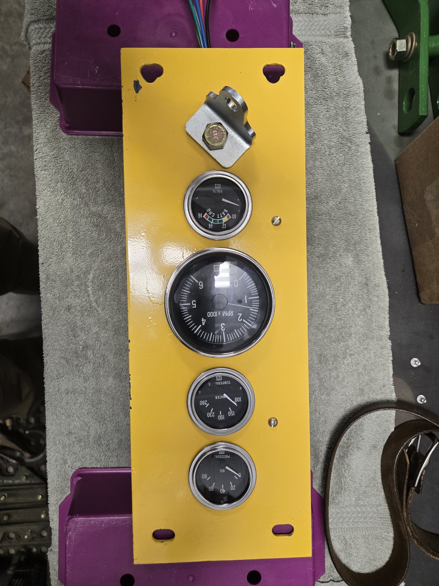
The engine vitals are on the left side with a seat belt bracket at the stock location. It will get a Deutsch 6 way DT connector:
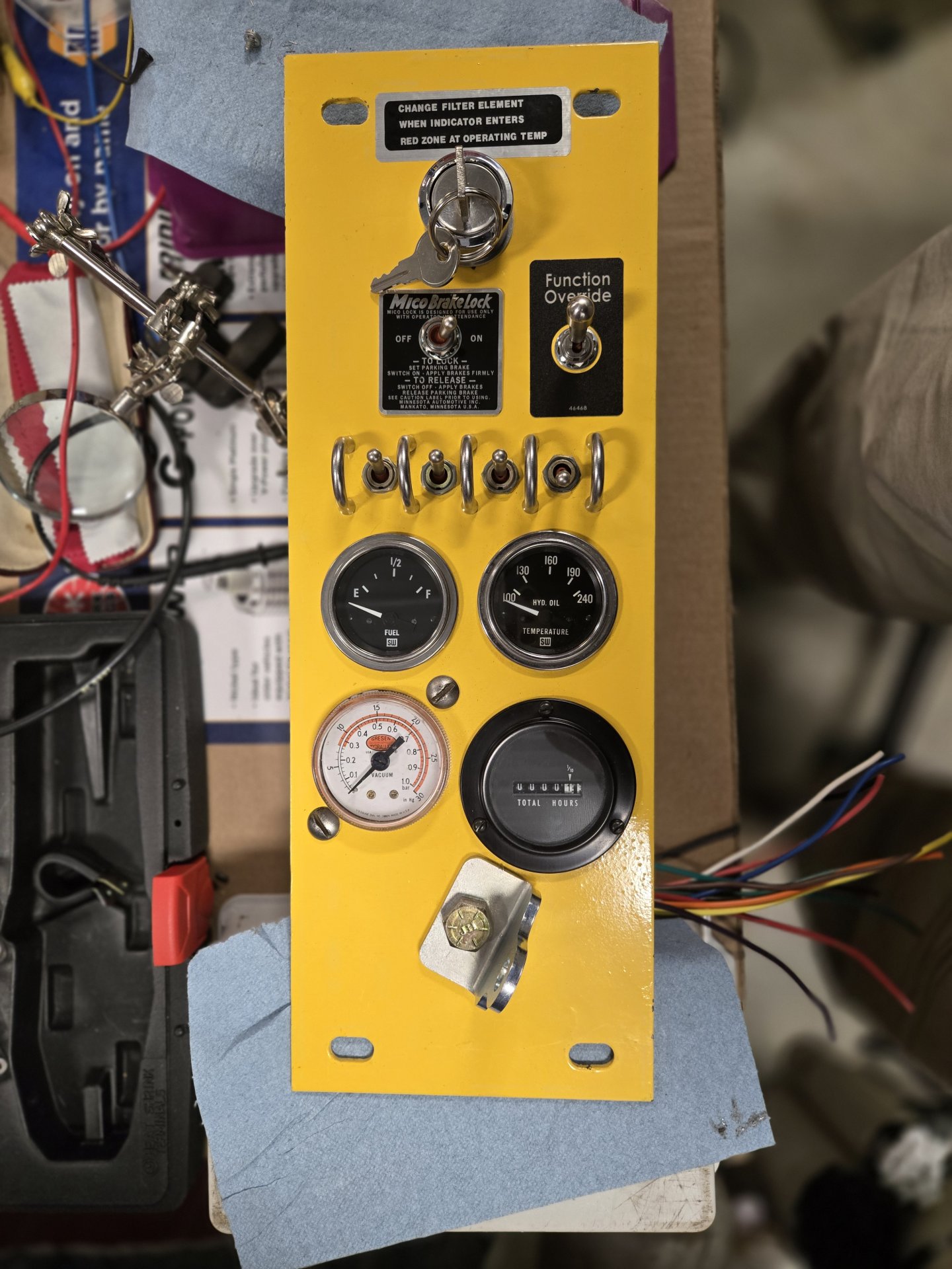
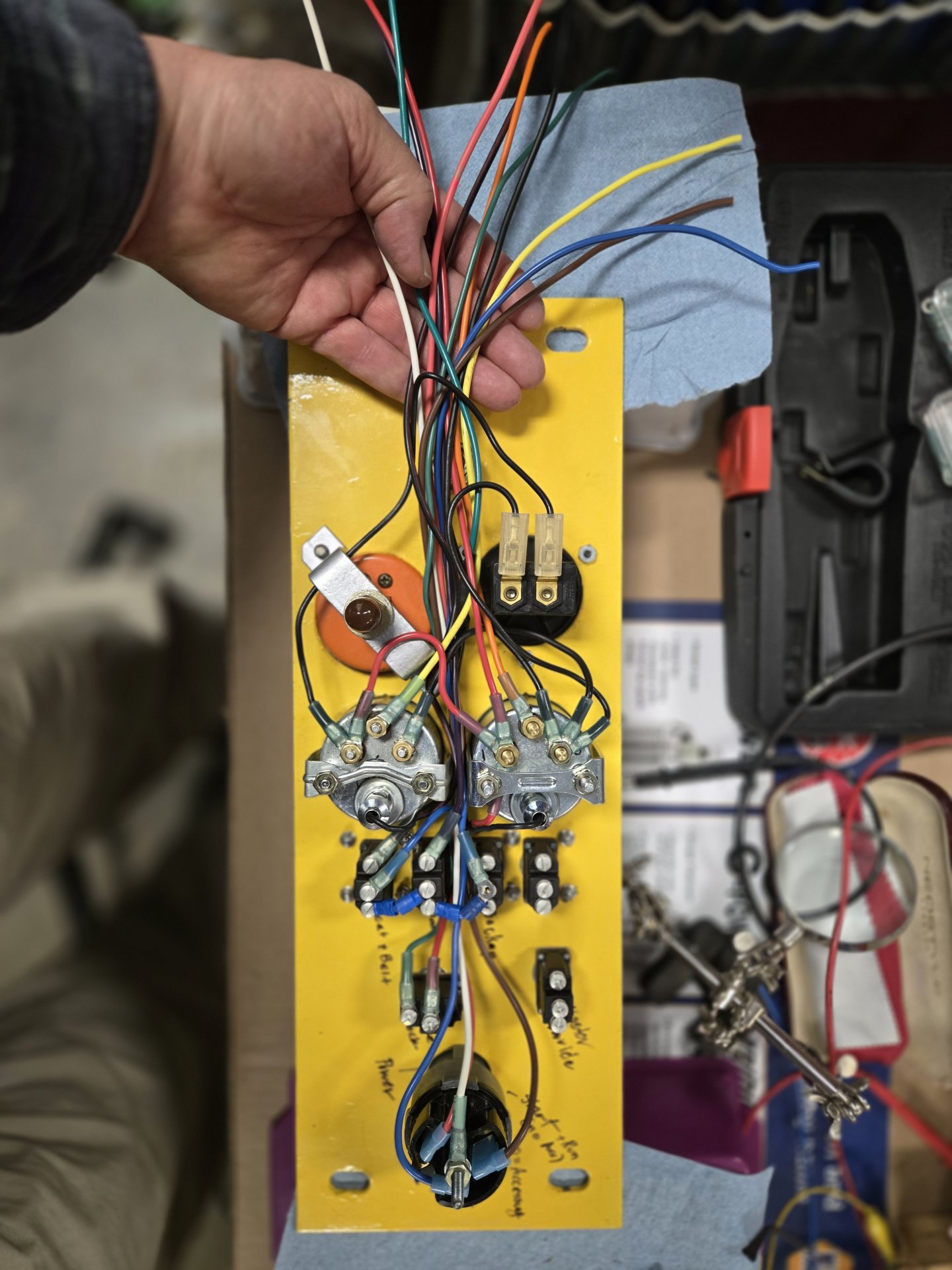
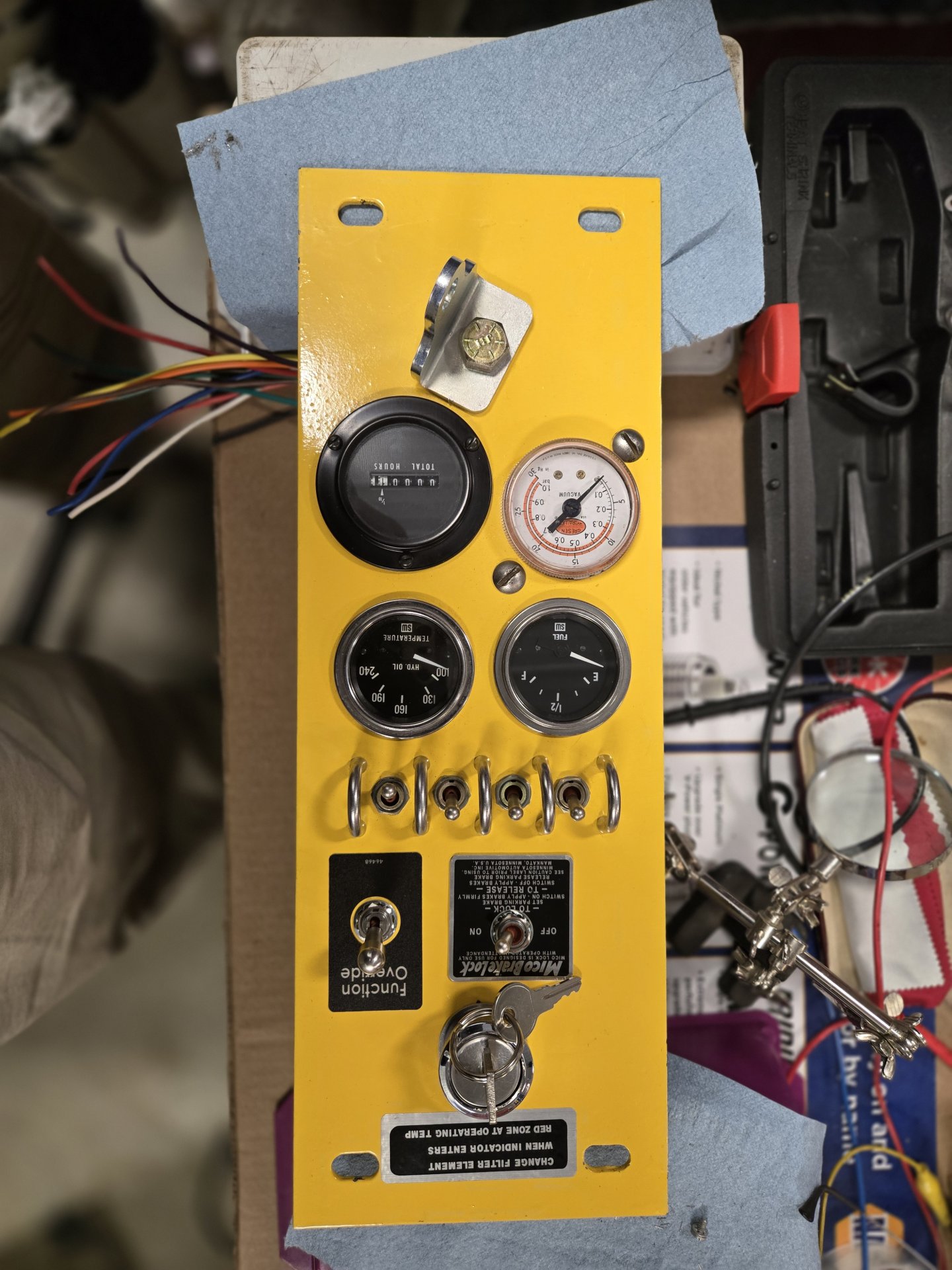
This right side is ignition switch, individual safety overrides, master safety override, brake lock, hour meter, hydraulic filter, hydraulic temperature and fuel level (more on that later). I ran out of wire colors so I'm waiting for gray and something striped to arrive in the mail. This side gets a 6 way DT connector for gauges and powered things, and a 12 way DT connector for ignition and safety's. The switches can individually override a safety. They include one for the seat (butt in the seat) and seat belt on (both wired in series), one for the door being open (if it is and you raise the boom, carnage of the cab door results) and a back up beeper. The master Function Override (closest decal I could find), overrides everything and allows direct power to the engine for it to run. It's from my old Navy/MC days where some vehicles had "battle override" switches to override everything and keep the vehicle running so you could escape if you were getting your butt shot at. I can see this might save my rear in a huge blizzard verses getting stock out in the boonies. It certainly risks equipment damage but that's part of the design. Oh, I also ordered some diodes that I'll have to put in to avoid the Function Override from back feeding the system.
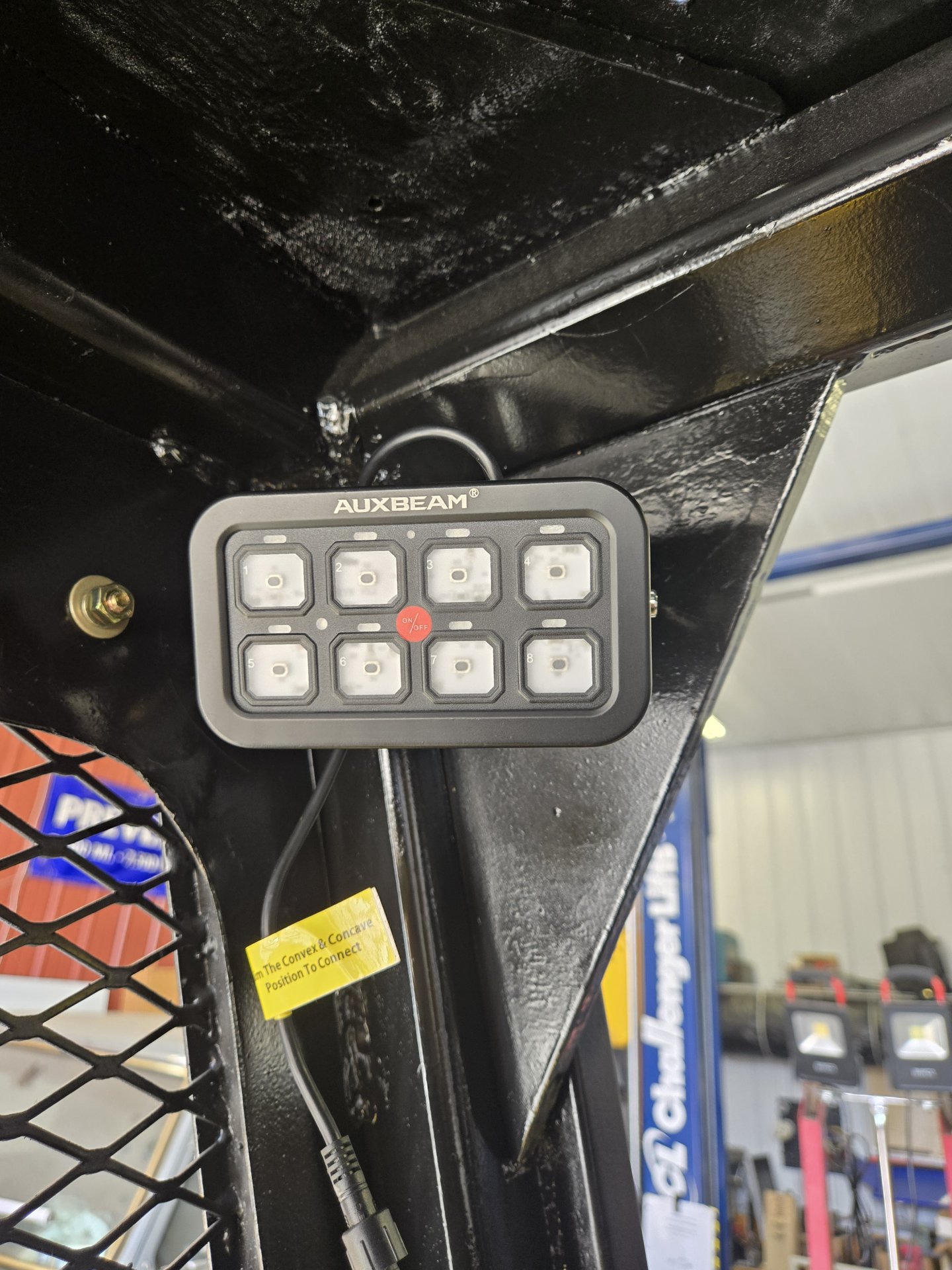
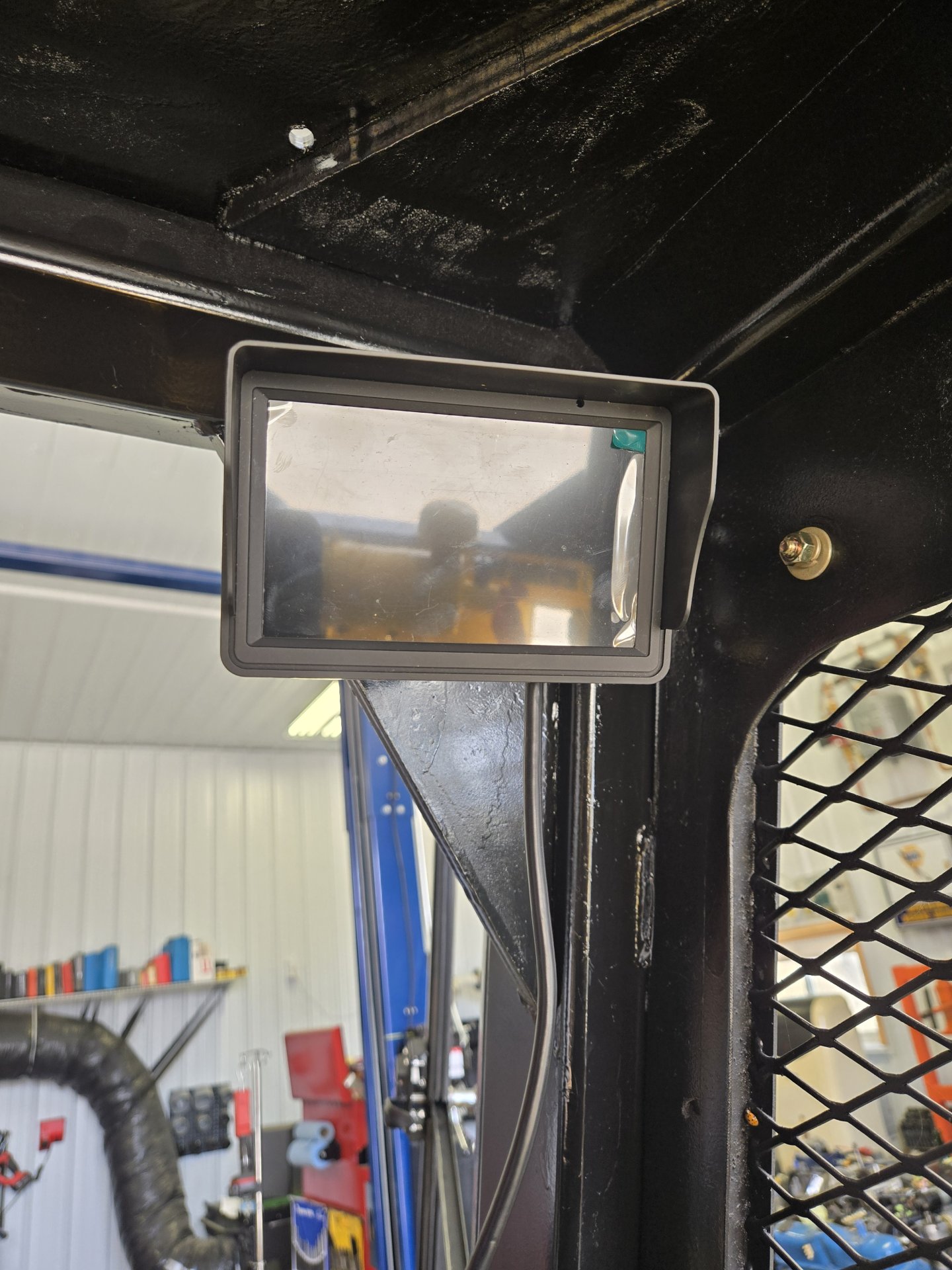
The master switch device is installed. It will operate the boom lights (and illuminate the gauges), forward light bar, rear light bar, forward and aft cameras, roof strobe, and other stuff I'm forgetting. Function inserts will cover each button. The camera monitor is on the right and can split the screen for both cameras, and I have it set up to auto trigger the rear camera when the backup beeper is active (both travel controls pulled back). It's in the next post as I have exceeded my 10 pictures per post.
I found an NOS boom lock and will either duplicate it for the other side or beg if someone has one for sale they don't want. I have a nice boom lock setup off a Case skid steer that I was intending to use until I found this. Anyone have one to sell?
Here's the status of the electrical.
The engine vitals are on the left side with a seat belt bracket at the stock location. It will get a Deutsch 6 way DT connector:
This right side is ignition switch, individual safety overrides, master safety override, brake lock, hour meter, hydraulic filter, hydraulic temperature and fuel level (more on that later). I ran out of wire colors so I'm waiting for gray and something striped to arrive in the mail. This side gets a 6 way DT connector for gauges and powered things, and a 12 way DT connector for ignition and safety's. The switches can individually override a safety. They include one for the seat (butt in the seat) and seat belt on (both wired in series), one for the door being open (if it is and you raise the boom, carnage of the cab door results) and a back up beeper. The master Function Override (closest decal I could find), overrides everything and allows direct power to the engine for it to run. It's from my old Navy/MC days where some vehicles had "battle override" switches to override everything and keep the vehicle running so you could escape if you were getting your butt shot at. I can see this might save my rear in a huge blizzard verses getting stock out in the boonies. It certainly risks equipment damage but that's part of the design. Oh, I also ordered some diodes that I'll have to put in to avoid the Function Override from back feeding the system.
The master switch device is installed. It will operate the boom lights (and illuminate the gauges), forward light bar, rear light bar, forward and aft cameras, roof strobe, and other stuff I'm forgetting. Function inserts will cover each button. The camera monitor is on the right and can split the screen for both cameras, and I have it set up to auto trigger the rear camera when the backup beeper is active (both travel controls pulled back). It's in the next post as I have exceeded my 10 pictures per post.
Attachments
Last edited:
OP
OP
OP
OP
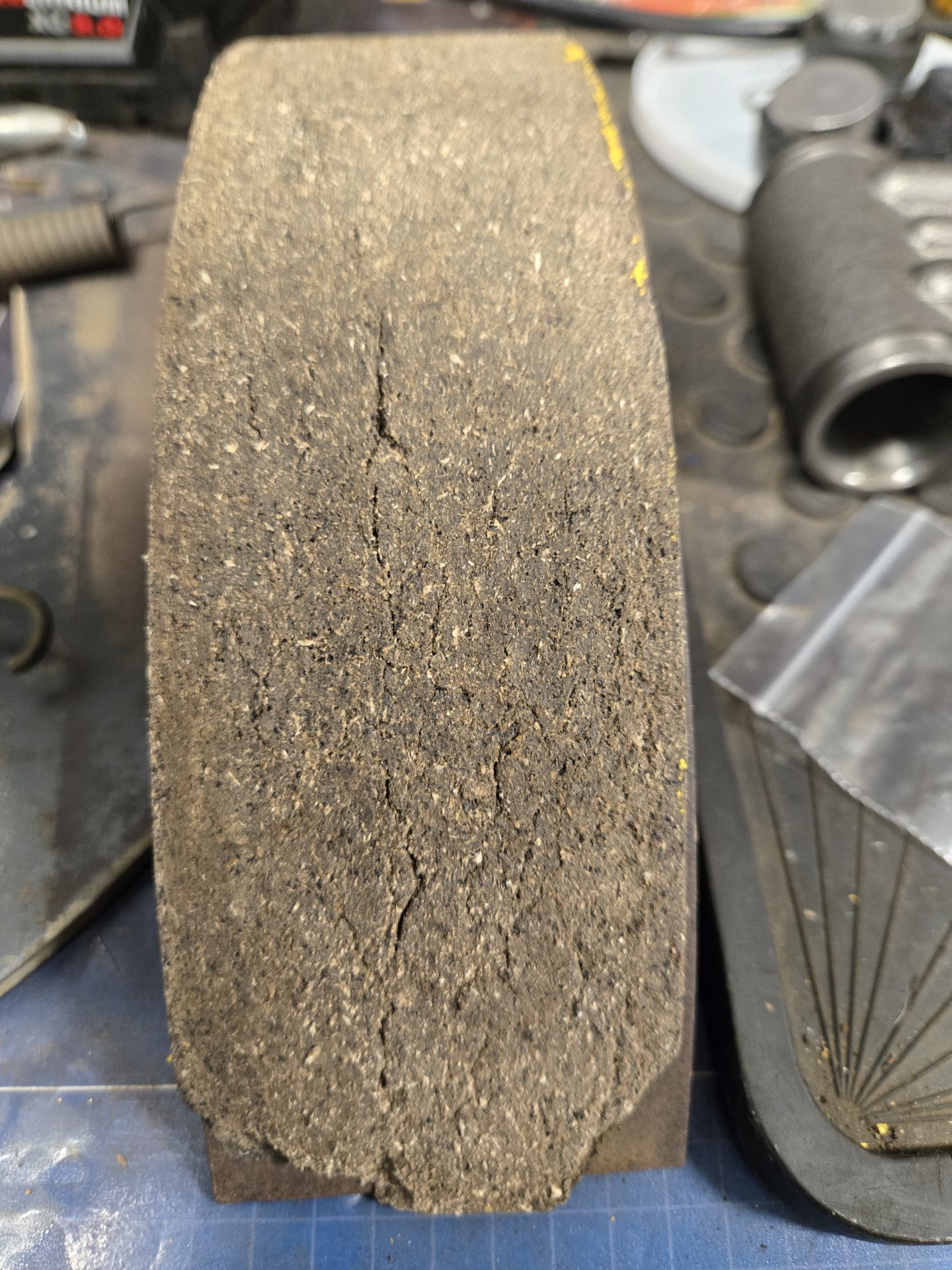
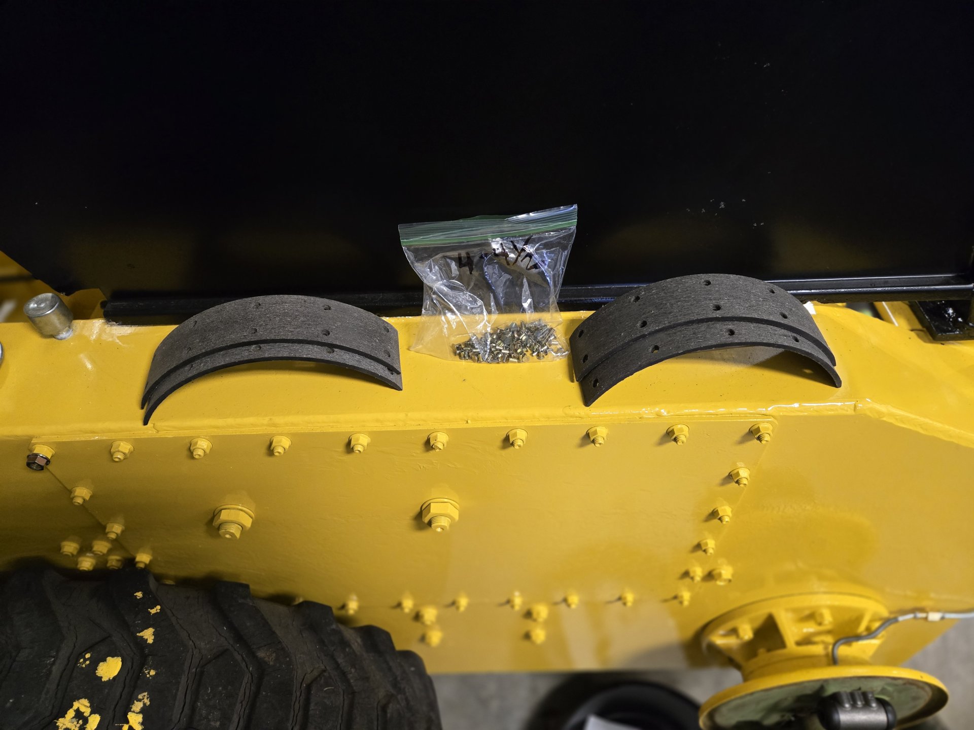
Brakes and electrical (with more pics). I went to finalize the right brake assembly and when I cleaned up the shoes and friction material - wearing a N100 respirator with the shoes inside my walnut shell blaster attached to a HEPA filtered vacuum - the friction material was cracking and delaminating from a lot of heat... and obviously asbestos. Of course I have to do the engineer thing and looked at it under a microscope. Yep, chrysotile. The other side I had previously "finished" had non-stock friction material riveted on and they were crooked, but I was willing to live with it. The right side has the stock bonded friction material. I searched the entire planet for someone to put new friction material on the shoes, no takers. So I ordered NOS pads (11" diameter by 2-1/4" wide) and rivets off ePay. They are asbestos too but I have no choice. When I get everything finalized, I post pics.
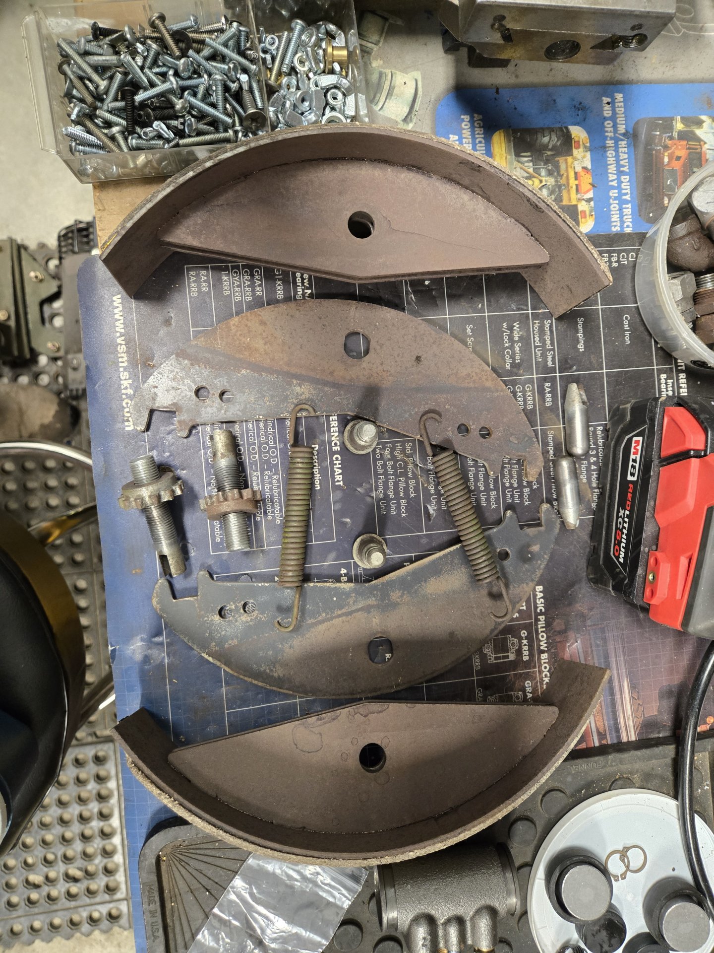
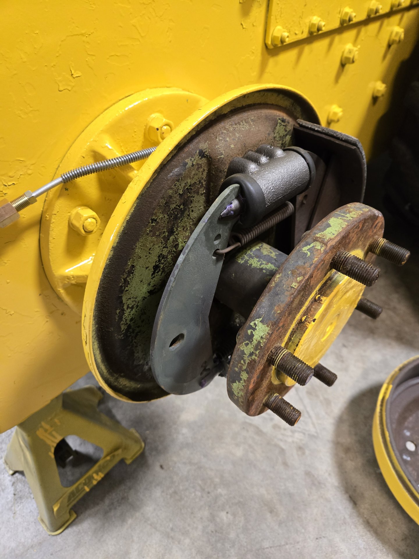
I think I finally figured out this brake shoe design. Remove the pin clip, push out the pin, and the shoe is removeable without removing the mounts, the springs, or disturbing the hydraulic system. ?????
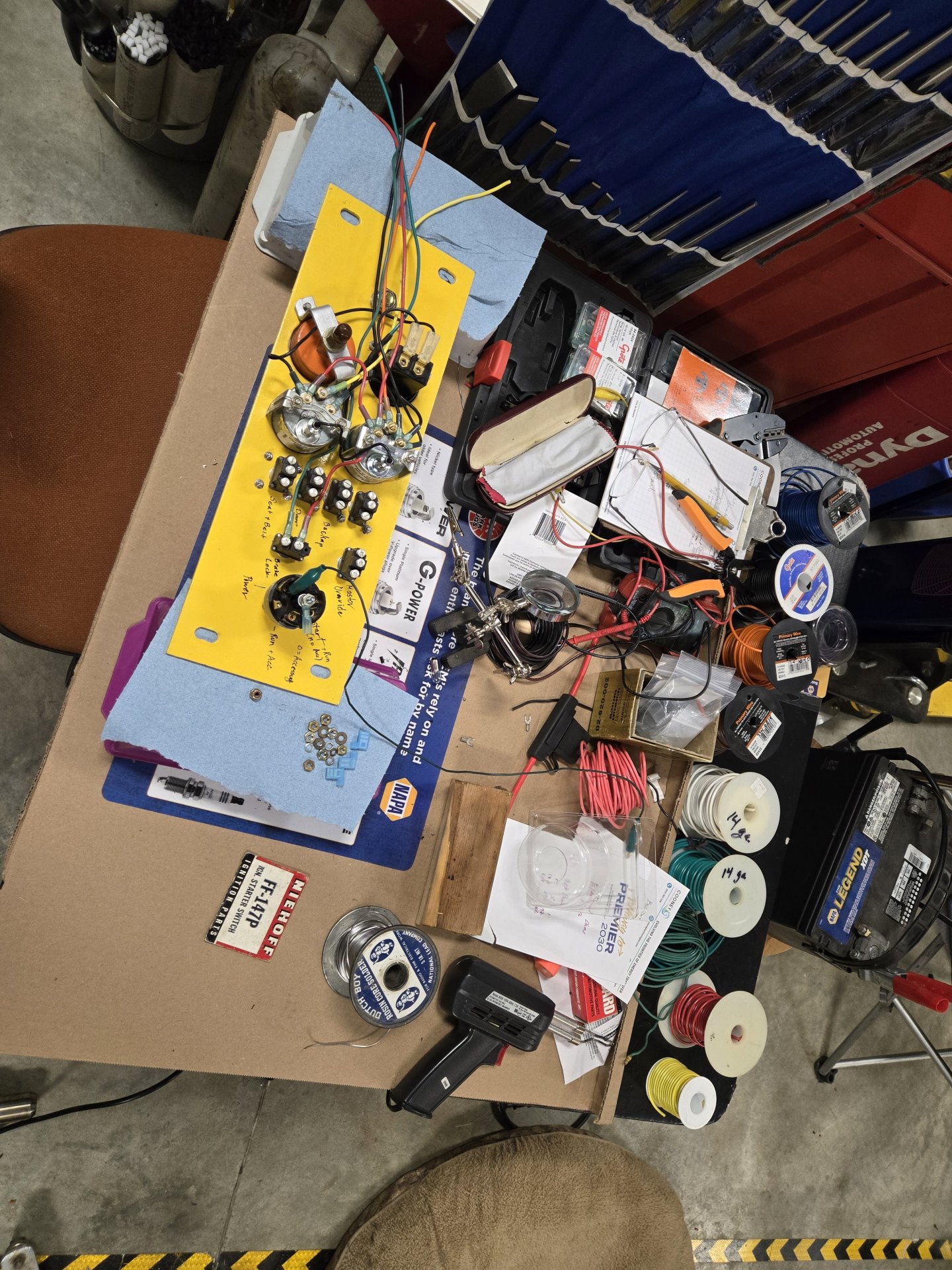
Here are pictures of wiring central that I couldn't insert above.
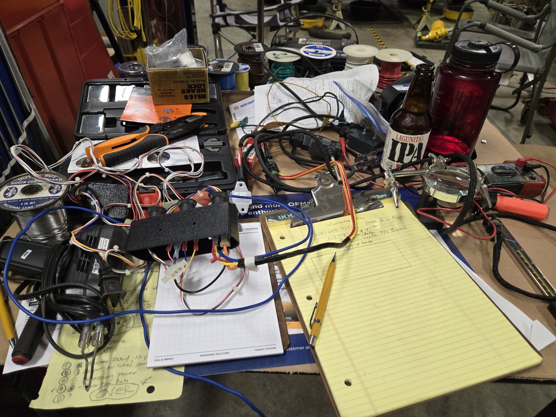
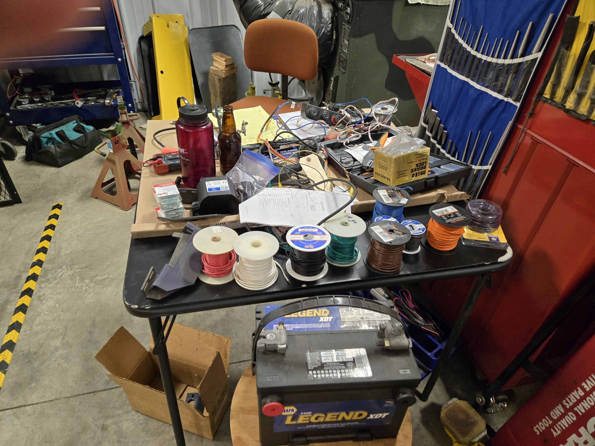
Al Jones
I think I finally figured out this brake shoe design. Remove the pin clip, push out the pin, and the shoe is removeable without removing the mounts, the springs, or disturbing the hydraulic system. ?????
Here are pictures of wiring central that I couldn't insert above.
Al Jones
Sapientoni
Well-known member
- Joined
- Jun 13, 2025
- Messages
- 103
Your passion for detail is refreshing. Your machine will be popular at the county fair, no doubt. When I was an industrial mechanic, we were having to clean/replace Raymond forklift brakes. I remember the per shoe cost being $99 each. I happened to see a set on the counter that had been relined at the local Clutch Rebuilder Service. They were $16 a piece. Later I discovered the plastic brake line hose failure (which was fluid drenching the shoes) was heat related from the brakes being constantly overheated. After I wrapped some aluminum foil from my sandwich around the hose, the failures stopped. Even later date, I learned from reading the operator manual, the operator's were not even supposed to be using the brakes! They were supposed to be using the electric control handle and "regeneratively" braking the machines for the most part.

BrianBryan
Member
That makes sense. My 1200 doesn't have brakes, so all I have is regenerative braking.Your passion for detail is refreshing. Your machine will be popular at the county fair, no doubt. When I was an industrial mechanic, we were having to clean/replace Raymond forklift brakes. I remember the per shoe cost being $99 each. I happened to see a set on the counter that had been relined at the local Clutch Rebuilder Service. They were $16 a piece. Later I discovered the plastic brake line hose failure (which was fluid drenching the shoes) was heat related from the brakes being constantly overheated. After I wrapped some aluminum foil from my sandwich around the hose, the failures stopped. Even later date, I learned from reading the operator manual, the operator's were not even supposed to be using the brakes! They were supposed to be using the electric control handle and "regeneratively" braking the machines for the most part.
OP
OP
Thank you for your comment. My intention is to work the dickens out of this machine when it's done. It's not intended to be a trailer queen. In fact, I love working on and fixing machines, but don't like operating them past the point of clearing the repairs and certifying it for work. So, my lovely wife gets to operate it and clear snow next winter.Your passion for detail is refreshing. Your machine will be popular at the county fair, no doubt.
 Here's one of the resets (1964 JD 4020) I did a few years ago. Tornado smashed it snapping off the final drives and doing extensive damage. So, after the repairs, my lovely spouse gets to cut, rake and bale our pastures.
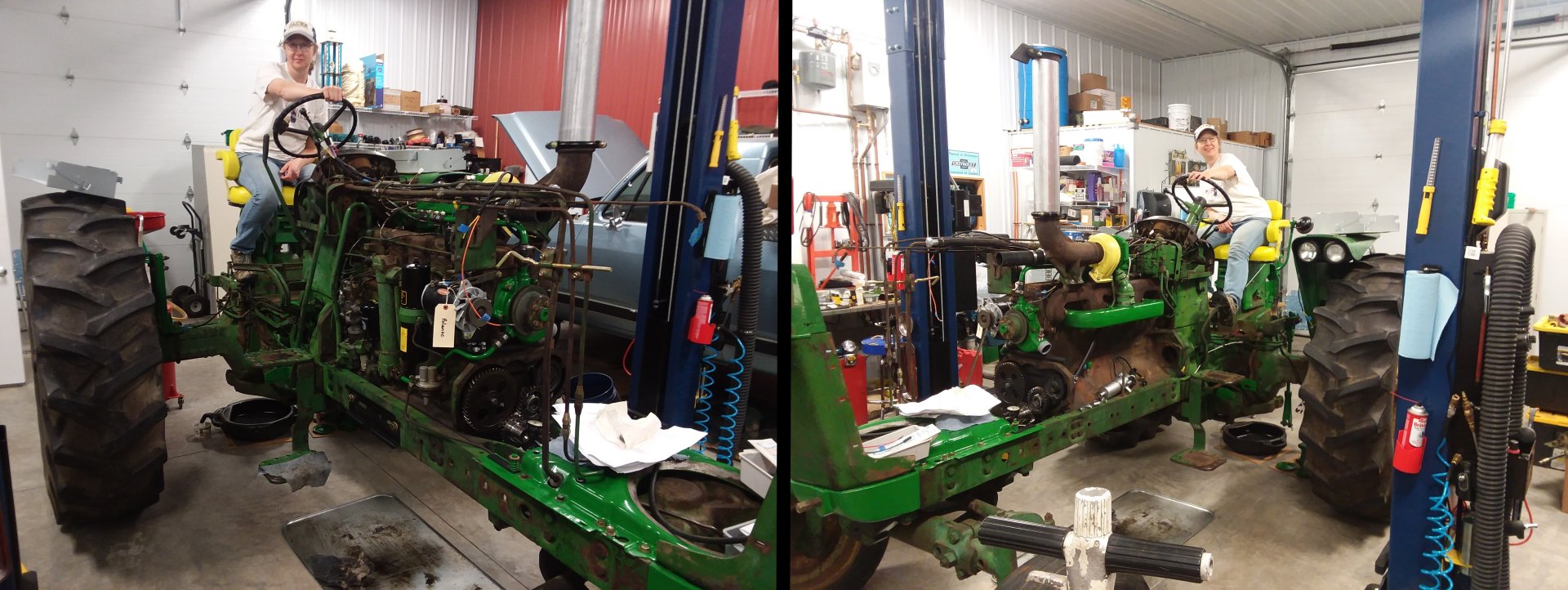
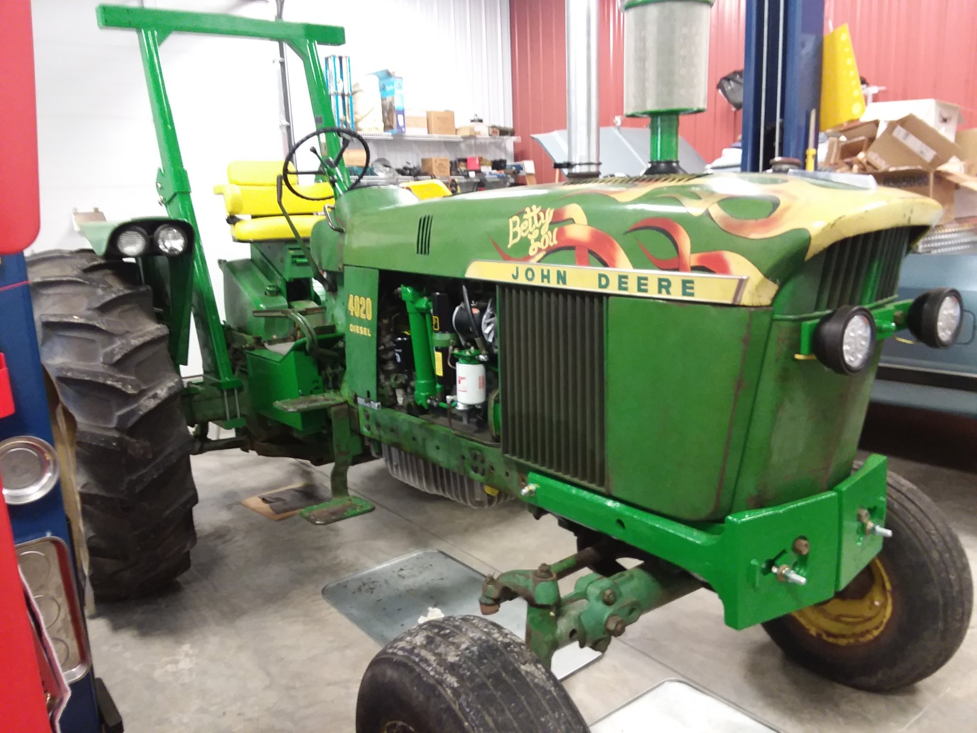
Al Jones
Hi Al, finally back on my rebuild and taking your advice, I think I glad I did.Torque convertor. Been working on that stuff. I found some cracked/split fittings on the adapter so I thought it best to go all the way. Everything is ready with the exception of a new or rebuilt torque convertor. Note there is a 50 psi relief valve attached to the adapter that attaches to the C-4 trans pressure pump. Photos follow with comments above.
Here's the 50 psi relief valve. Flow direction is in blue. To adjust the valve, remove the cap (orange), slightly loosen the jam nut (red) and you'll see a pair of slots to adjust it. I forgot to take pictures, but the valve is simple: a spherical ball that rests on a seat with a spring behind it. Screw adjustment "in" for higher pressure. The second photo is how I adjusted it. With air and a regulator. I put 120 psi to it and it was solid at 52 psi. It fluttered as the pressure was reduced below 50 psi, but I think that won't happen with fluid in it.
View attachment 10627 View attachment 10628
The operator's manual seems to harp on keeping this valve adjusted. I could not find anything on the planet to use as replacement. Any fluid/hydraulic relief valve is expecting much higher pressures so anything down at 50 psi, I couldn't find. The ball and seat had some wear, but it doesn't seem to leak before it hits 50-ish psi. Adjusting this on the machine would suck.
The parts book calls the fittings "socketless adapters", Gates calls them "Brass Field Attachable Couplings". The working pressure is 300 psi when using the correct hose, plenty for the torque convertor. Everything is NPT. Pushing the hoses on is tough, but it can be done, that's what Gates says to do. My fingers hurt. Here is the final product ready to go in the machine. Note the two brown caps. The long bass/copper thing is a screen assembly on the suction side. It's supposed to be serviced (cleaned) periodically. That cap will get a hose that goes to the hydraulic fluid reservoir. The other one is excess fluid that dumps into the right final drive. So, this only gets screened fluid, not filtered. Don't like it, but... You can see how the relief valve is plumbed into the concoction.
View attachment 10629 View attachment 10630
If anyone has an opinion on NOS torque convertors with an early 1970s date code, please share. My choices are NOS Gehl or rebuilt. They are both are within about $50 of each other. My machine did not have the original convertor in it. It had a car one, either Pinto or Capri.
One of the prior owners had replaced the adapter with a higher serial number than mine. I first panicked because the higher serial number has a different spline count than my serial number range. So what they did was just replace the adapter. After counting splines, everything was good to go. This machine from the gear box to the front of the engine had seen some prior carnage. I'm putting everything back to stock with new parts.
Al Jones
Brookings, SD
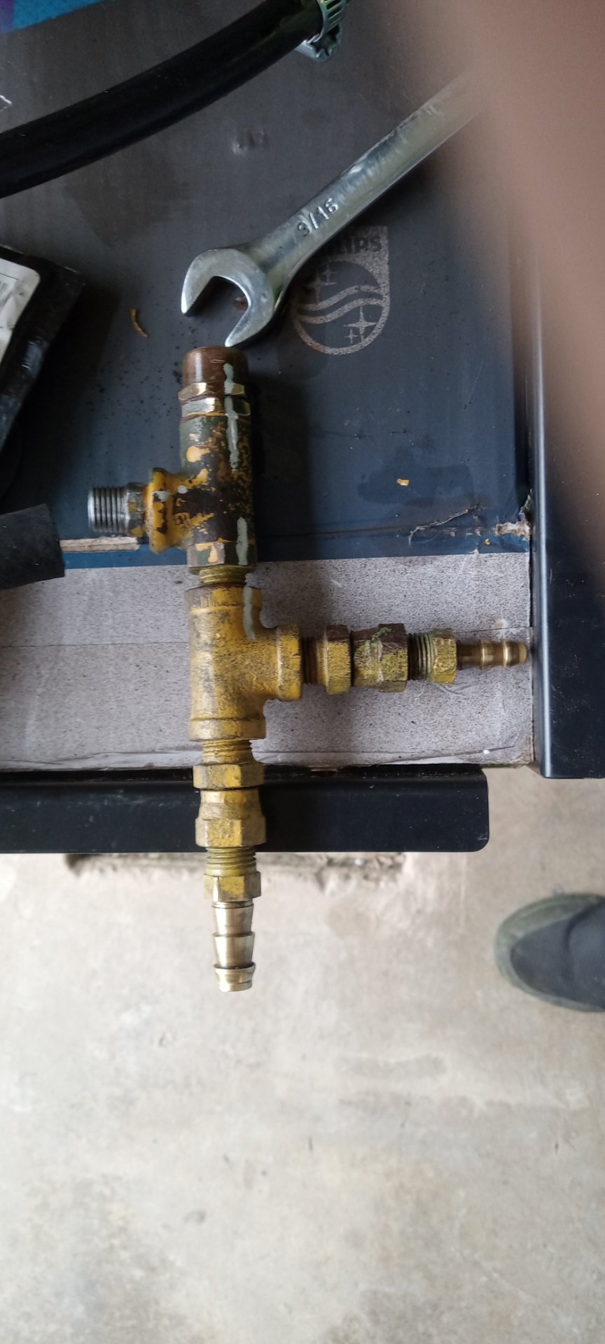
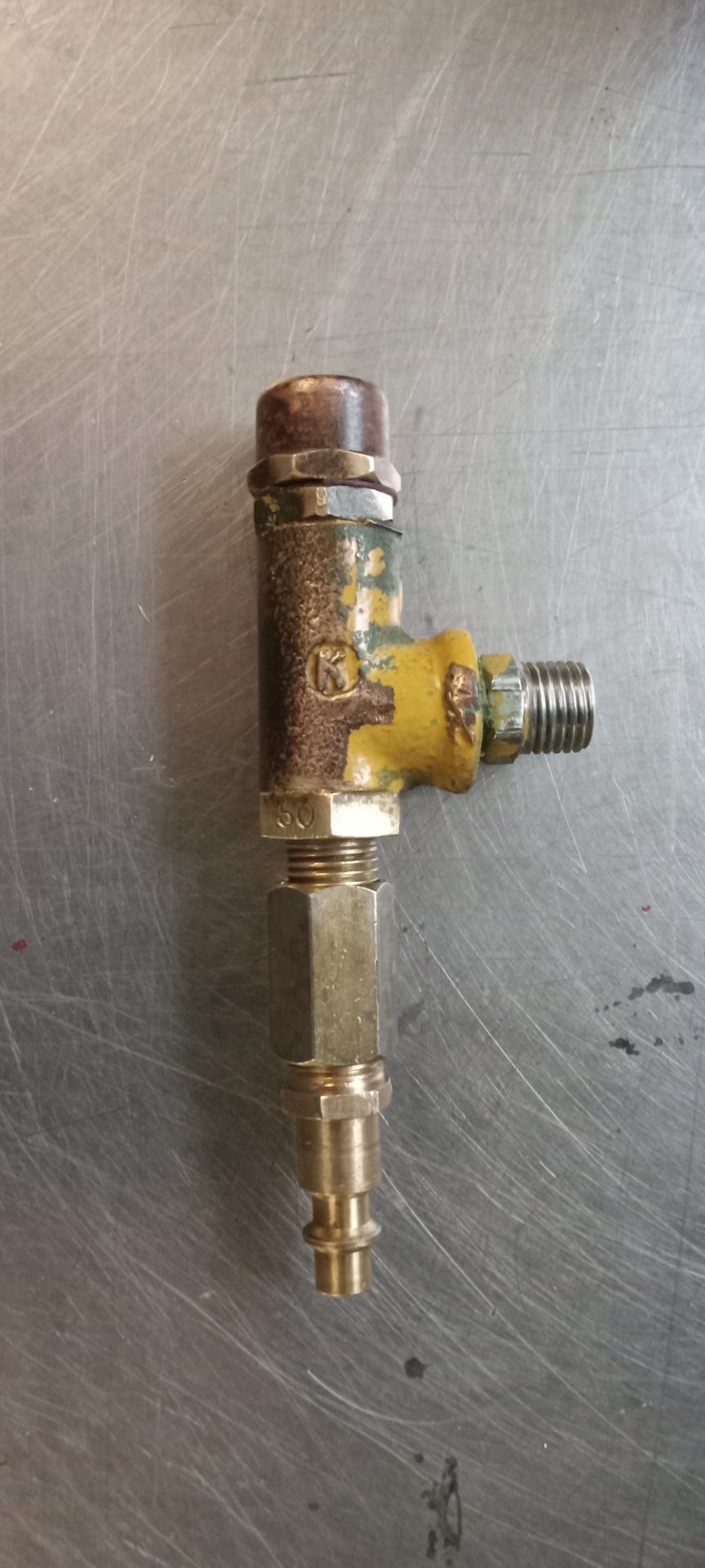
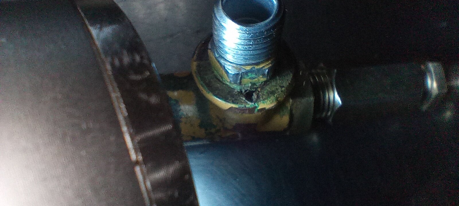
I have taken the transmission charge pump pressure relief valve off to test and inspect. The first photo showes how it is cobbled together before removing parts to install air line fitting. The second shows my setup for air plumbing. The third show possible defective valve body with triangle shaped hole or crack in surface next to fitting that goes into pump directly.
I cant tell if air is escaping from suspected triangle crack yet because the whole thing is hissing. Delivery of less than 50lbs and air comes out exit and more does the same. What am I looking for , no leakes at below 50? Please advise. Steve
Attachments

Bonez
Well-known member
Thats cool, Once I get my machine I think I am going to paint it and have some decals made.... WALL-E themed LOLI was going to save this for later, but I'm a old, NOS parts junkie. This original, NOS, full decal kit for the Ford Torque Convertor, gasoline, 1700 model was my biggest parts score to date. It even has the red pony decals. I'm an old timer and we didn't get to play with stickers like younger folk get to now. So I have a soft spot for stickers and love 'em.
View attachment 9699
View attachment 9700
The title of this thread is now inaccurate. It should be a restoration, not a reset. I can't help myself. I'm still within the budget my wife set for me, but I'm way over the estimated time limit. I'm so glad she's patient.
Having fun,
Al Jones
OP
OP
Steve,Hi Al, finally back on my rebuild and taking your advice, I think I glad I did.
I have taken the transmission charge pump pressure relief valve off to test and inspect. The first photo showes how it is cobbled together before removing parts to install air line fitting. The second shows my setup for air plumbing. The third show possible defective valve body with triangle shaped hole or crack in surface next to fitting that goes into pump directly.
I cant tell if air is escaping from suspected triangle crack yet because the whole thing is hissing. Delivery of less than 50lbs and air comes out exit and more does the same. What am I looking for , no leakes at below 50? Please advise. Steve
Sorry for the delayed reply, I'm traveling. Wasn't the hole leaking like crazy before you took it apart? Yes, it is a bypass valve so it should not hiss while bench testing up to 50 psi, then open as more air is added, I went up to 120 psi and it was a solid at 52 psi on my valve. Yes, I do think your valve body is damaged. I'd suggest taking it all apart to see if the plunger or seat is damaged, or if the spring is broken. If not, you have two choices, repair the one you have or search the Internet for one.
When I get home, I'll check my stuff to see if I have anything that might help you.
Al Jones
Ok I'll check again and take apart. The hole may have been leaking but I thought it was the pump seals. Also the movement of the machine was weak so that might suggest it was leaking. The male nipple blocks view of the hole so I might have been fooled. I'll report back when I know more. You seem to be the only person I can find that knows anything about this valve and its workings. Thanks SteveSteve,
Sorry for the delayed reply, I'm traveling. Wasn't the hole leaking like crazy before you took it apart? Yes, it is a bypass valve so it should not hiss while bench testing up to 50 psi, then open as more air is added, I went up to 120 psi and it was a solid at 52 psi on my valve. Yes, I do think your valve body is damaged. I'd suggest taking it all apart to see if the plunger or seat is damaged, or if the spring is broken. If not, you have two choices, repair the one you have or search the Internet for one.
When I get home, I'll check my stuff to see if I have anything that might help you.
Al Jones


