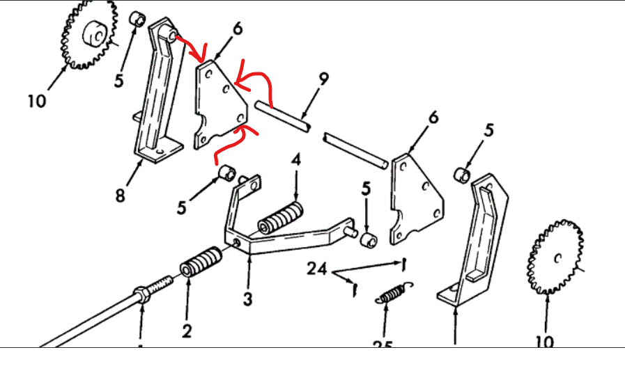
I'm pretty sure there is no braking action taking place if something doesn't engage the cogs to stop rotation. What I could not figure out is what should contact the cogs. Looking at the parts diagram, If the 1/2" rod is mounted in the middle holes of the two plates that swing forward and backward, I believe it would pull the rod into the cogs. I'll have to measure, but I expect 1/2" rod fits perfectly into the space between each tooth. My bent piece, whatever it's called does not have the rollers, that go over pins, they are solid steel and do not fit into the cogs. Nothing did, but that 1/2 rod might be the missing part... They want $50 for part 9 here. (Yikes.) So if it's 1/2" and 11" long I'll just get that locally and drill holes for cotter pins and use a couple washers in front of those.
I'm guessing part 9 goes into the middle hole of the side plate as I drew on the image. Then when part 3, which bolts to the bottom hack hole is pulled forward, the rod would engage the cogs (I think) locking the motors... I need to clean everything out I'll see if that hole lines up with the cogs as I suspect. I'll take pics when I can do that.


![Pampers Sensitive Baby Wipes, Clinically Proven, Fragrance Free, Unscented, Water Based, Hypoallergenic, Multi-Use, Hand Wipes 336 Wipes Total (6X Flip-Top Packs) [Packaging May Vary]](https://m.media-amazon.com/images/I/41KLBHu9CAL._SL500_.jpg)