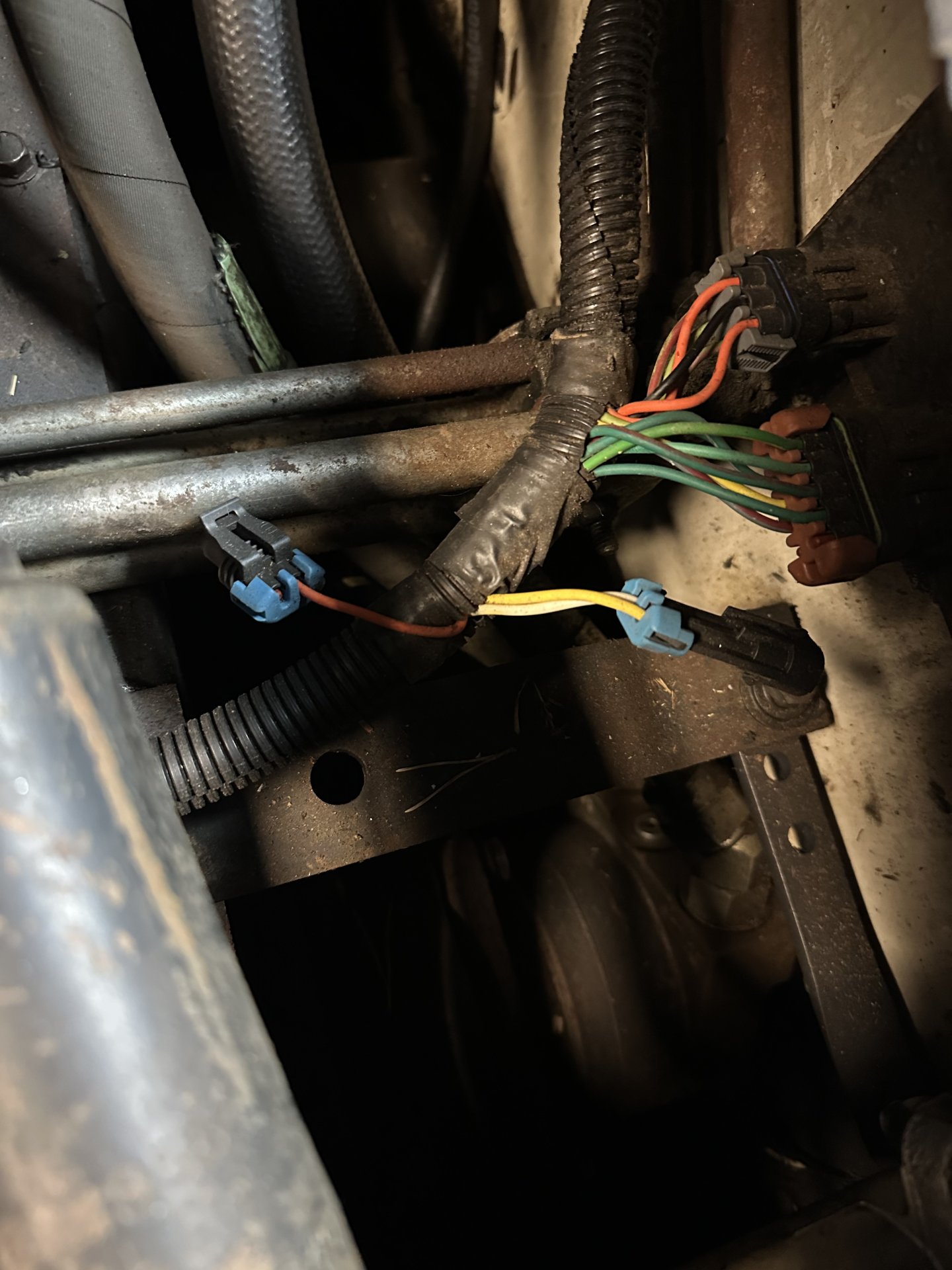
Good evening. new to the newer bobcats i think i have a 95. i bought a plow for my 753 and am trying to get the angle to work. i had to buy a new auxiliary switch that is under my boss system because it was so corroded and wouldn't work. put the new switch in and now the lights light up but the plow still wouldn't angle. so i lifted the cab and the wires for the stick switches were just hanging there. i have a bunch of empty connectors on this harness and cant figure out where they go. my color on my wires differs from all the ones in the manual. This harness looks like it has been replaced at some point because it doesn't look that old. did they change the wiring colors?
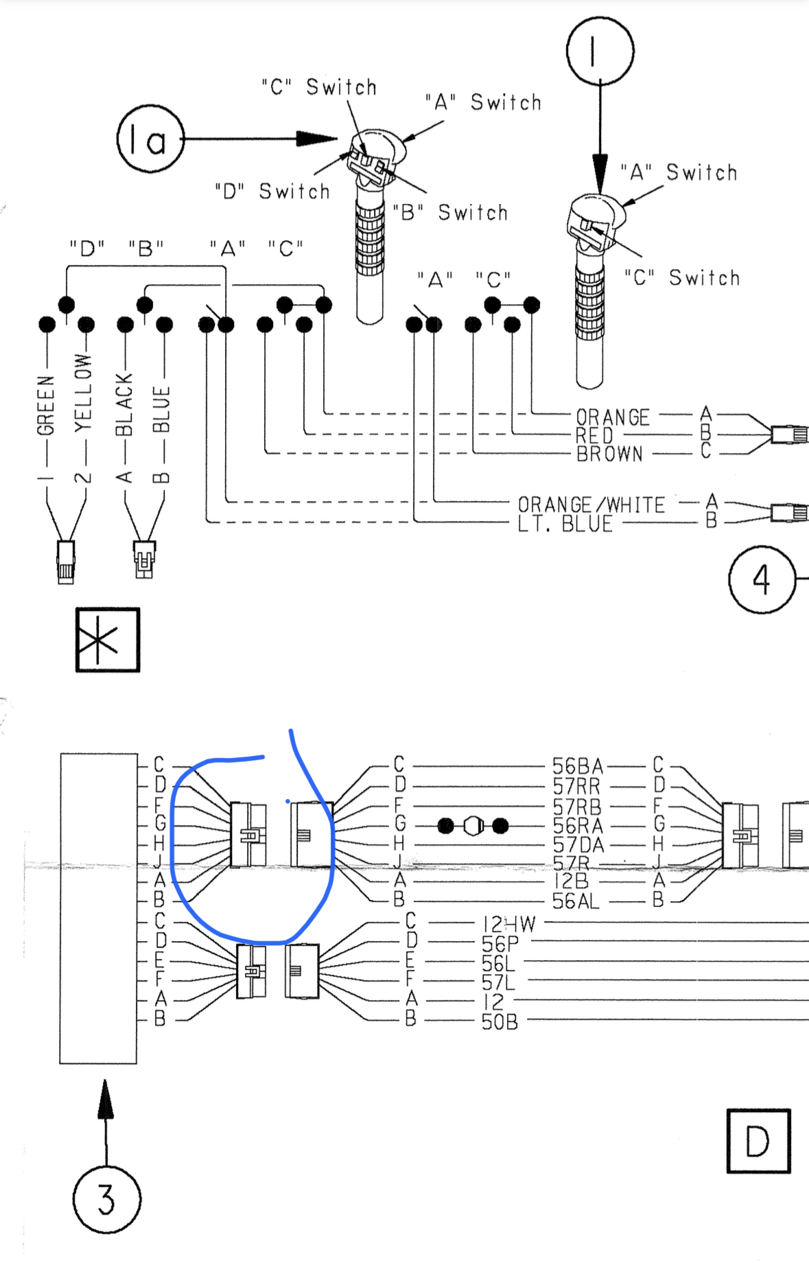
The manual says the colors should be
green/red
yellow/white
yellow
dk green/lt green
yellow
lt blue/red
orange
dark green
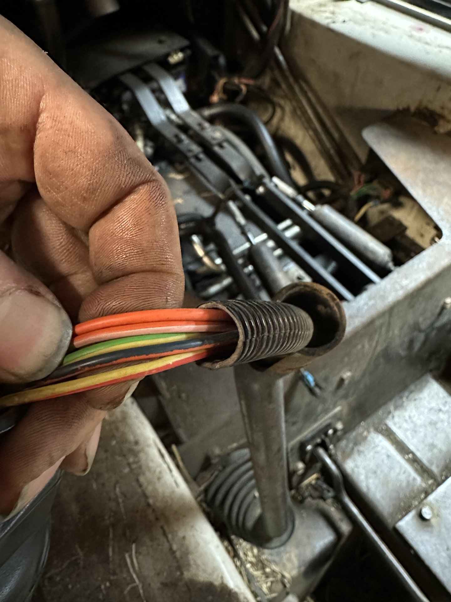
i have
green/yellow
green
green/red
green
green/red
green/white
yellow
gray/red
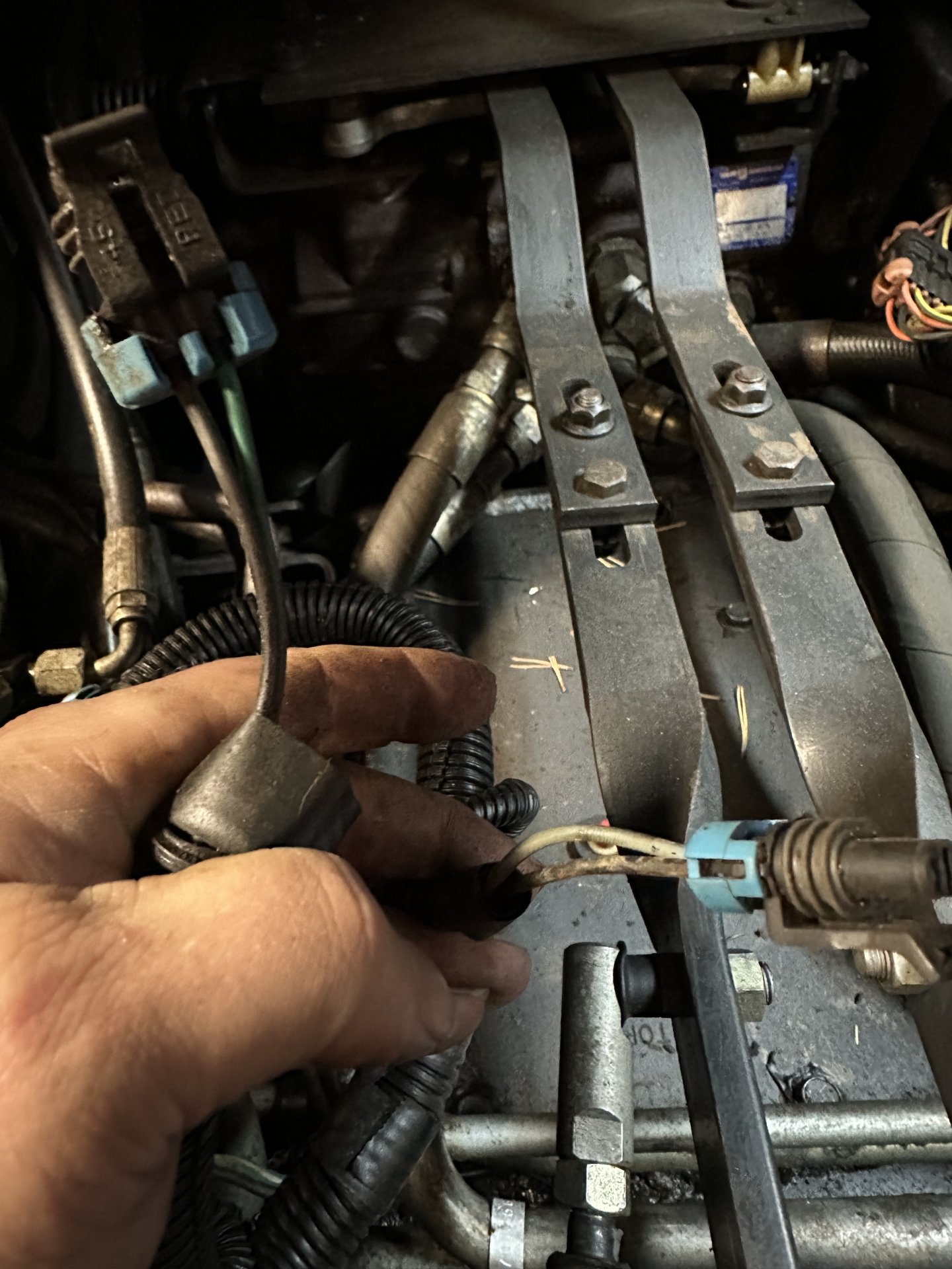
Connector in question the bigger connector on the auxiliary control module. My module is located under the cab mounted on the left side. I was going to go by the pin letters on the connector but A and K are blank with rubber plugs but the manual says a should have a pin. So i am very confused. This is a non high flow 753 with a serial 508611787. i gave it to my bobcat dealer and they said they cant do anything with it it doesnt come up.
Sorry for the bad typing i am on my garage computer and some buttons dont work anymore lol.
The manual says the colors should be
green/red
yellow/white
yellow
dk green/lt green
yellow
lt blue/red
orange
dark green
i have
green/yellow
green
green/red
green
green/red
green/white
yellow
gray/red
Connector in question the bigger connector on the auxiliary control module. My module is located under the cab mounted on the left side. I was going to go by the pin letters on the connector but A and K are blank with rubber plugs but the manual says a should have a pin. So i am very confused. This is a non high flow 753 with a serial 508611787. i gave it to my bobcat dealer and they said they cant do anything with it it doesnt come up.
Sorry for the bad typing i am on my garage computer and some buttons dont work anymore lol.


![Pampers Sensitive Baby Wipes, Clinically Proven, Fragrance Free, Unscented, Water Based, Hypoallergenic, Multi-Use, Hand Wipes 336 Wipes Total (6X Flip-Top Packs) [Packaging May Vary]](https://m.media-amazon.com/images/I/41KLBHu9CAL._SL500_.jpg)