Hi
@stevec,
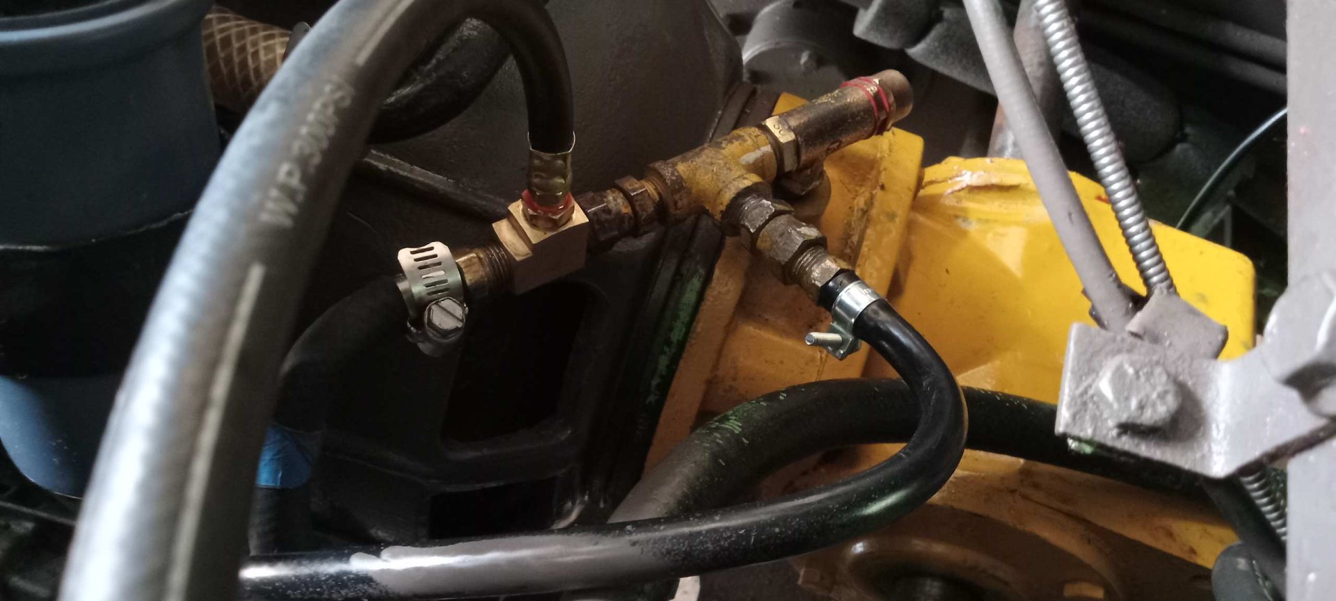
I'm back and was able to rewatch your videos on a computer screen. I'd like to post some content here on the charge pump and the bypass valve, and what I think is going on - in the hopes that it helps others along the way. If you don't want to read this, here's what I think: I think your by-pass valve is fine, it's not designed to prevent internal leakage, it's designed to keep a steady 50 psi behind it in the direction of flow.
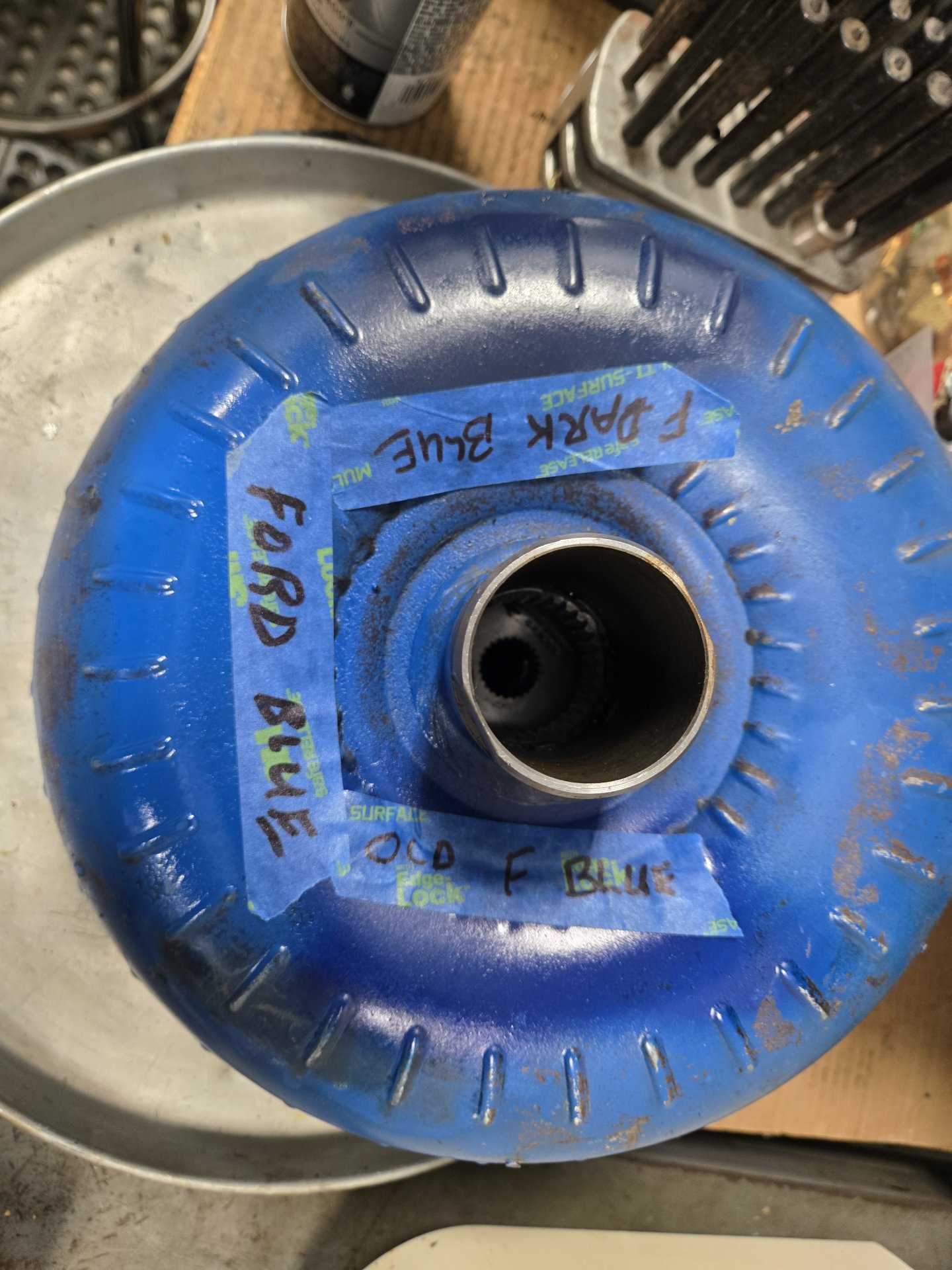
Here's a little technical content on the Ford C-4 transmission - your charge pump (which is normally called a pressure pump), torque convertor, bell housing, etc. are all Ford C-4 parts. The charge pump produces fluid pressure up to 300 psi. **Line Pressure** from the pump can spike to 150 to 200 psi and is used in the C-4 transmission case to control shifting, clutch pressure, etc. In our case, it is killed (0 psi) by passing it back to the final drive cavities. The **charge pressure** is a reduced pressure that is used to fill the torque convertor and keep it "coupled" to the pinion gear. In this case, it's a preset design pressure to maximize performance, longevity (I hope), etc. - it does not physically "lock-up" the torque convertor. What's the pressure? In our case, I think it's 50 psi. It gets a little more complicated in that all 1964 to 1981 charge pumps have a built-in 90 psi by-pass valve to protect the torque convertor from "ballooning". If the torque convertor sees over about 100 psi, it stretches in the direction of the crankshaft and will wipe out the thrust bearing in short order. I think the charge pump cast adapter is way more beefy so I wouldn't expect any damage in that direction. So, OMC installed that little 50 psi bypass valve and that is the pressure used in the torque convertor. That's why they harp on keeping it adjusted. Too little pressure, it will prematurely wear out the friction materials in the torque convertor by slipping too much. To much, and ballooning can occur.
With all that, some fluid leakage across the valve (like years) shouldn't be an issue **as long as there is 50 psi behind the valve** as that is what is feeding the torque convertor through another passage in the cast adapter. From what I could see, the ball in your valve is in better shape than mine. So I think leakage at pressures below 50 psi is fine as long as that pressure is maintained. So I actually think your valve is fine as long you can adjust a constant bypass pressure across it. If you do lap it for a better seal, I think you'll have a better product.
My suggestions for you: First, put your pressure gauge right up at the valve where it needs to be, then increase pressure across the valve and adjust it to 50 psi. Then check the valve up to about 100 psi to make sure it doesn't develop any additional pressure behind the valve. My valve leaked internally too, and it looks like about the same as yours, but that little of fluid bypass shouldn't hurt anything. I've seen pictures on the internet where people permanently install a pressure gauge at that little valve, so that tells me it's that much more important. And yes, JB Weld or do something with the triangular hole in the valve body. I'd suggest removing the fitting, cleaning the body really good and inspect it. You mentioned a crack and now is a good time to address it. I did not see at what pressure your valve was initially set at. Do you know? That would help your diagnosis. I also hope you're aware that all this (pump, valve, convertor, etc.) do not have a formal filter. It's supposed to pass through a screen in a brass housing before entering the convertor stuff. Did you take that apart to see if it's restricted? One guy I talked to said his was and after he cleaned it, it solved a lot of problems. The C-4 transmission has 40 micron filter but the screen is way bigger than that. I guess OMC was going to rely on the volume of filtered fluid through the high pressure hydraulic system.
I hope this detail helps. If you ever have to get into your charge pump, let me know and I'll post more detail and photos that might help. What I know about this stuff is luck. I'm resto-fying a 1971 Ford Bronco for my wife and swapping the manual 4 speed for... a built C-4 transmission, and overhauled the transmission myself. Total coincidence.
If anyone has suggestions, changes or corrections, let me know and I'll make them.
Good luck!
Al Jones


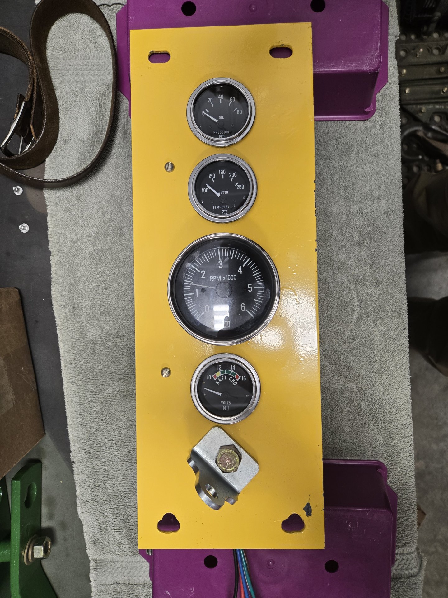
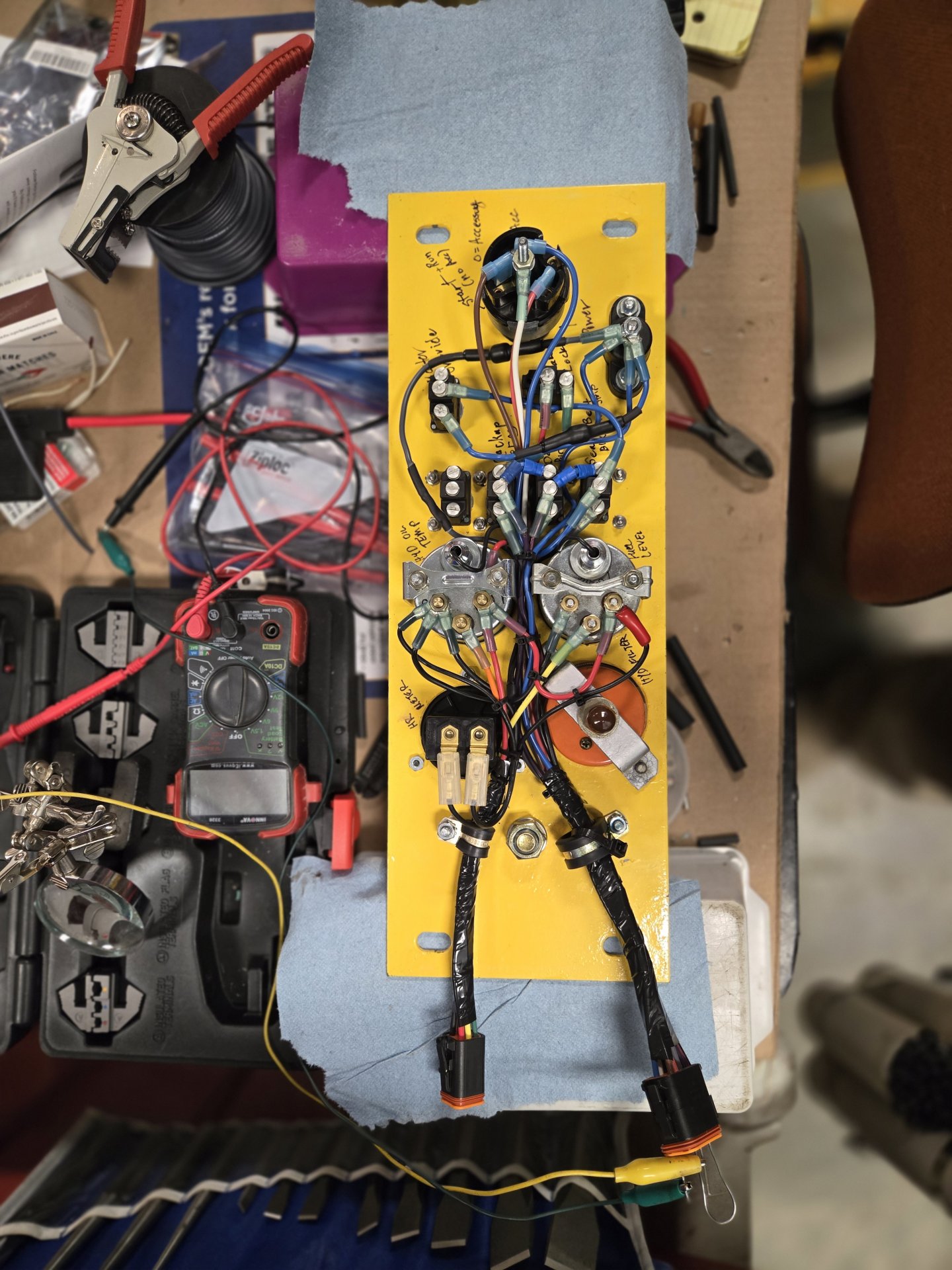
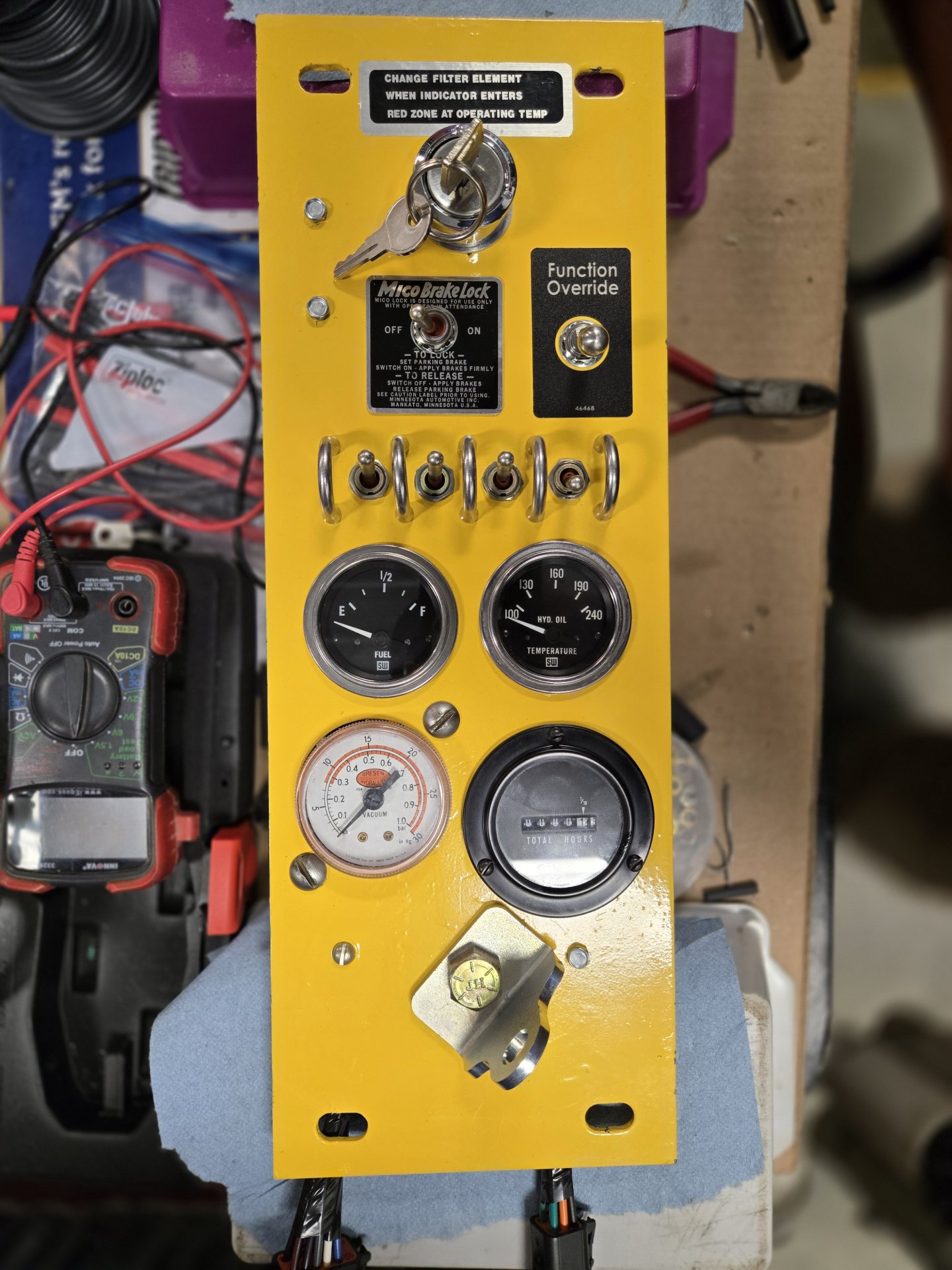
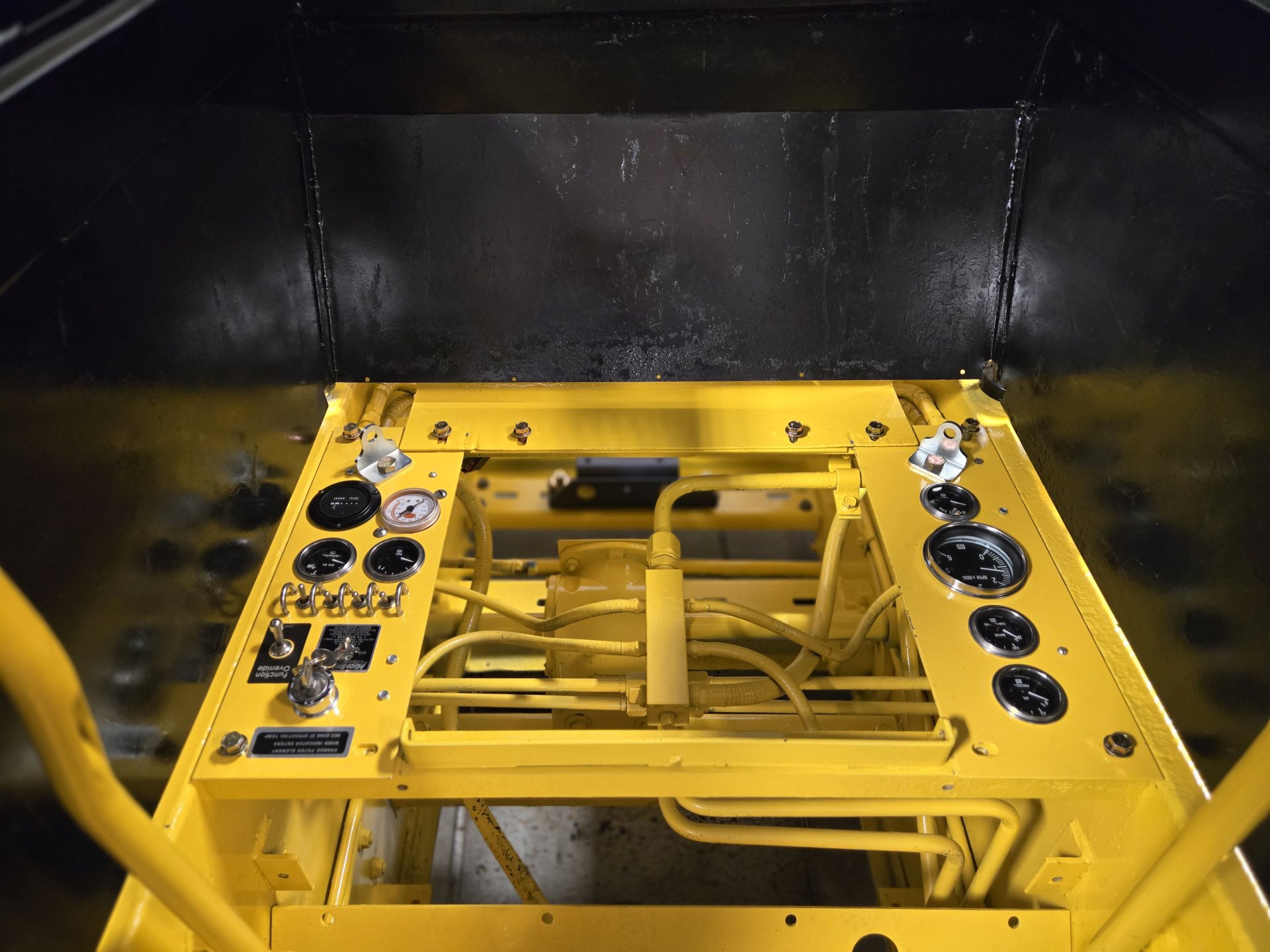
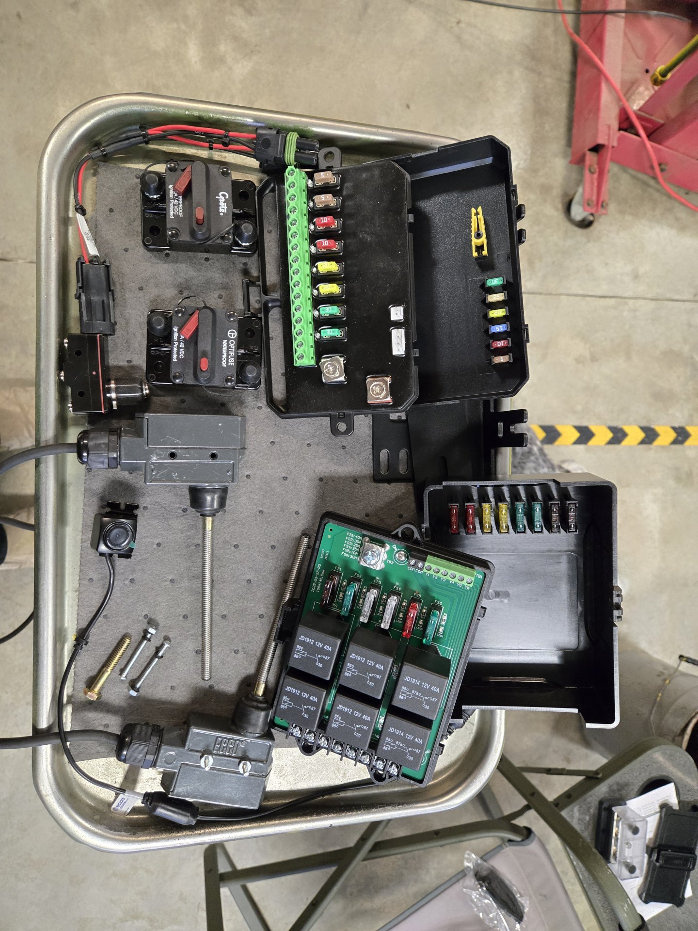
 as I want capabilities for other things down the road. One button is reserved for the horn.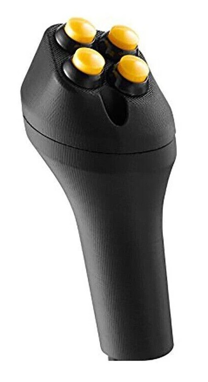


![Pampers Sensitive Baby Wipes, Clinically Proven, Fragrance Free, Unscented, Water Based, Hypoallergenic, Multi-Use, Hand Wipes 336 Wipes Total (6X Flip-Top Packs) [Packaging May Vary]](https://m.media-amazon.com/images/I/41KLBHu9CAL._SL500_.jpg)