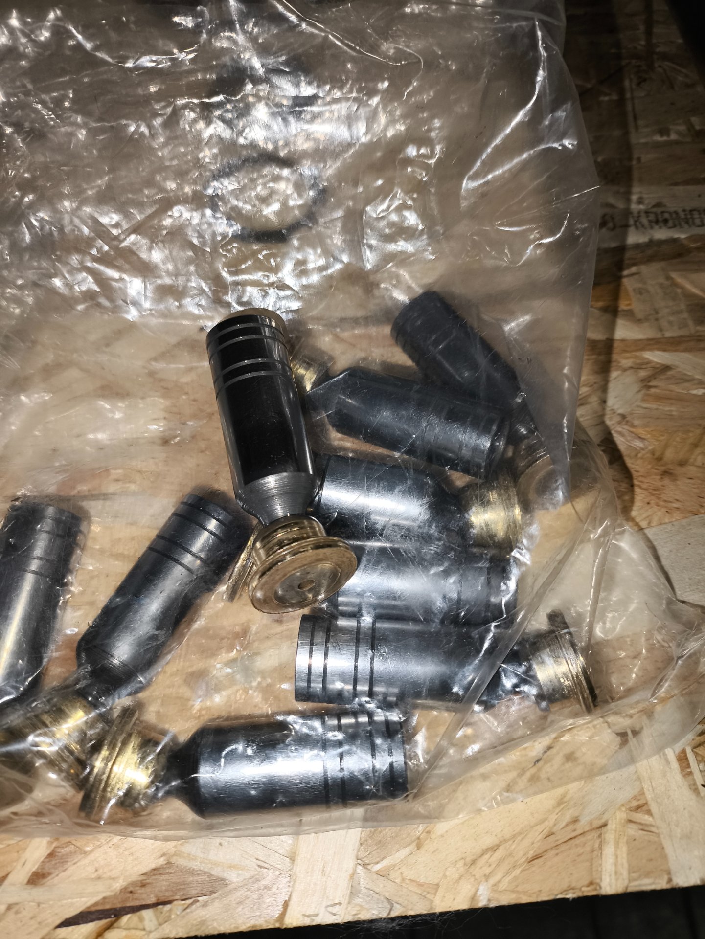
Bobcat 825 – Right side loses drive under load, loud noise. suction & charge pressure drops to zero

Skidsteer Forum - Bobcat, New Holland, Case, John Deere

Help Support Skidsteer:

Alex_SKS

Member
Joined
Dec 31, 2025
Messages
13
City & State/Province
Latvia, Riga
Hello everyone,


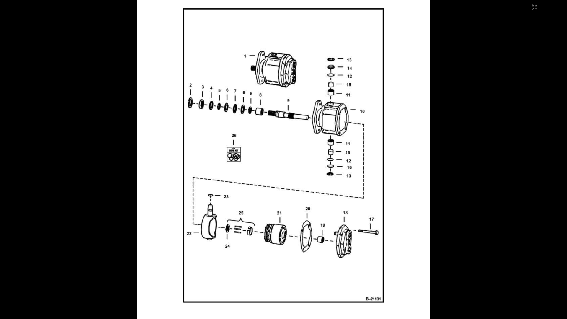
I’m troubleshooting a drive issue on an old Bobcat 825. This is my first time working with a hydrostatic drive system, so I’m learning as I go and trying to diagnose it correctly.


Problem description:
The right side drive moves under very light load, but as the load increases, it suddenly loses drive.

Even under light load, the right side produces a very loud whining / cavitation-like noise, loud enough to be uncomfortable. When the right side loses drive, this noise almost disappears.

If I keep the drive lever engaged after the loss of drive and wait longer, a different sound appears — a strange noise that resembles light metallic knocking or contact, which is concerning.

There is one more behavior that concerns me.

When the right side loses drive under load, if I keep the drive lever engaged for a few seconds (around 5 seconds), the machine sometimes starts to jerk or hop violently, almost like it is oscillating.

What feels especially unsafe is that releasing the drive levers does not immediately stop this behavior. In those cases, I have to shut the engine off to make it stop.

After restarting the engine, with the levers released, everything behaves normally again.

I’m not sure if this points to a control issue, pressure instability, or severe internal leakage, but I wanted to mention it as it seems relevant.


The left side works normally and does not show these symptoms.

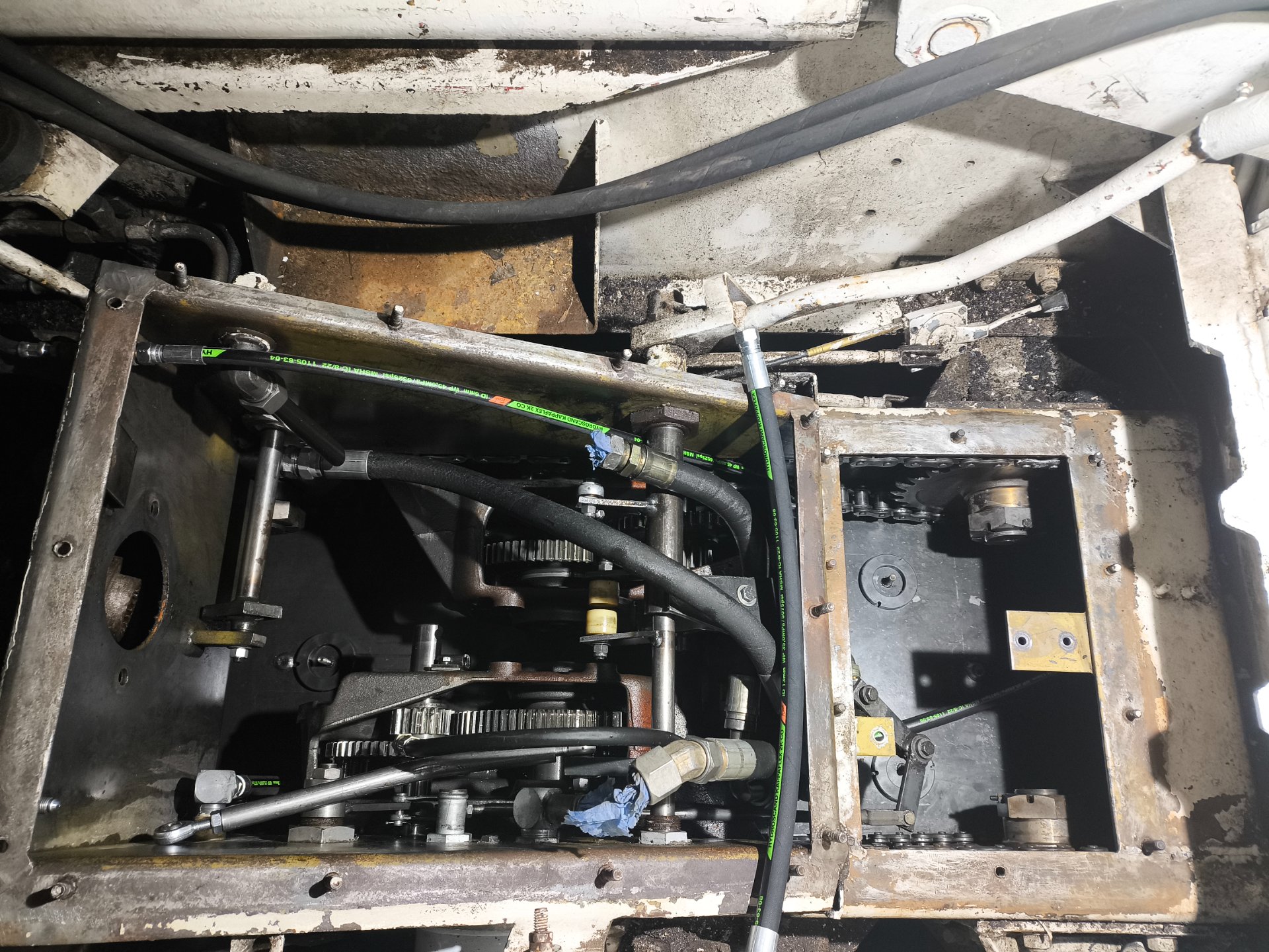
I have studied the service manual, installed pressure gauges, and started measuring suction and charge pressures. I’ll post the measured pressure values and photos in the replies below.

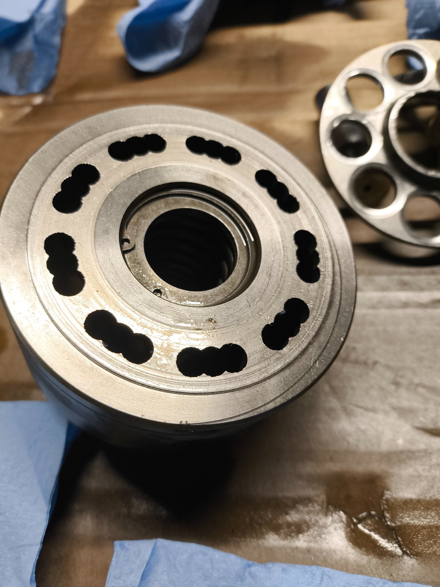
I have also removed and disassembled the right drive motor and would appreciate advice on evaluating internal wear.

I’ll add more details and photos in the replies below to keep things organized.

Thanks in advance for any guidance.
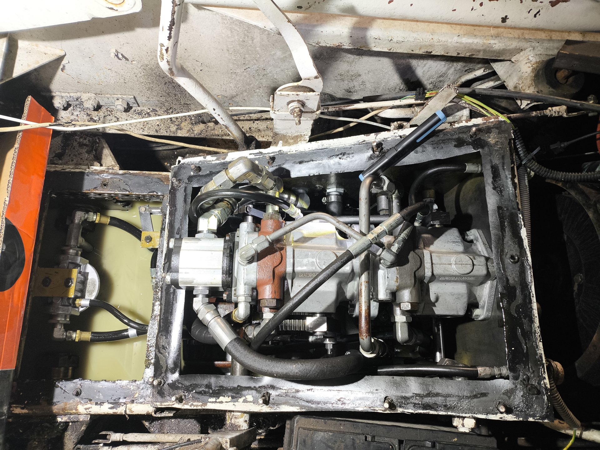
IMG_20251213_173950.jpg


IMG_20251224_150016.jpg


I also suspect possible water contamination in the hydraulic oil.

I can’t say how much water is present, but the oil color does not look healthy.
 
Last edited:
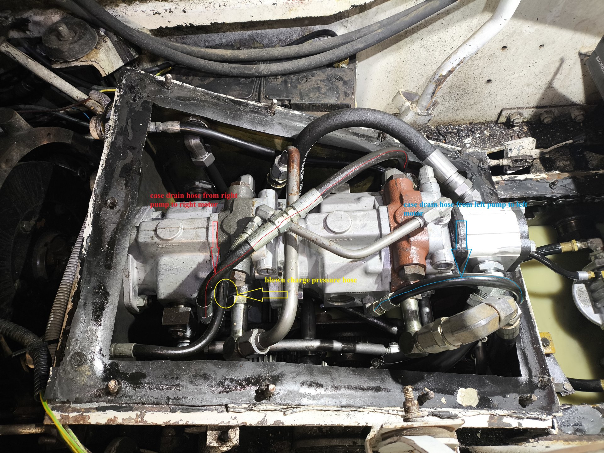
Here are the pressure measurements I’ve taken so far.

Hydraulic oil approx. 50 °F.


Suction pressure
  • Engine idling, no levers engaged: ~9 PSI
  • Left side drive at low power: slight drop to ~8 PSI (no issues observed)
  • Right side drive at low power: slight drop to ~8 PSI
  • When right side loses drive under load: suction pressure drops rapidly close to 0 PSI
According to the manual:
Charge pump inlet (suction) pressure:
  • Normal inlet pressure: 15–20 PSI
  • Minimum allowable inlet pressure: 4 PSI


Charge pressure
  • Engine idling, no levers engaged: ~100 PSI
  • Left side drive at low power: no significant drop noticed
  • Right side drive at low power: no significant drop noticed
  • When right side loses drive: charge pressure drops rapidly toward 0 PSI
According to the manual:
Charge pressure (at idle RPM):
  • Correct charge pressure is 90 PSI

This pressure collapse happens exactly at the moment when the right side stops moving.


How critical is it if the inlet pressure is below the specified 15 PSI at idle and without load?
 
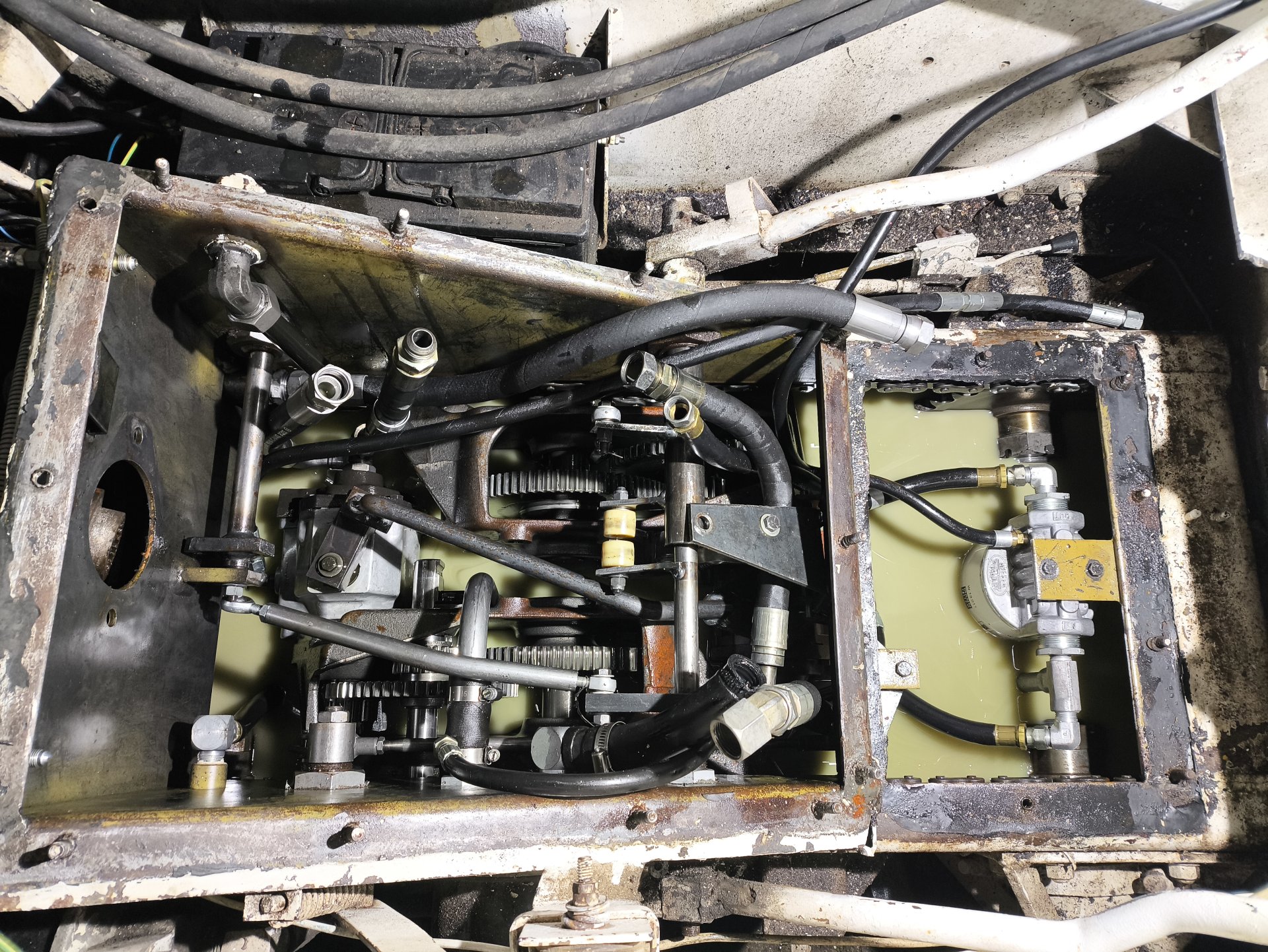
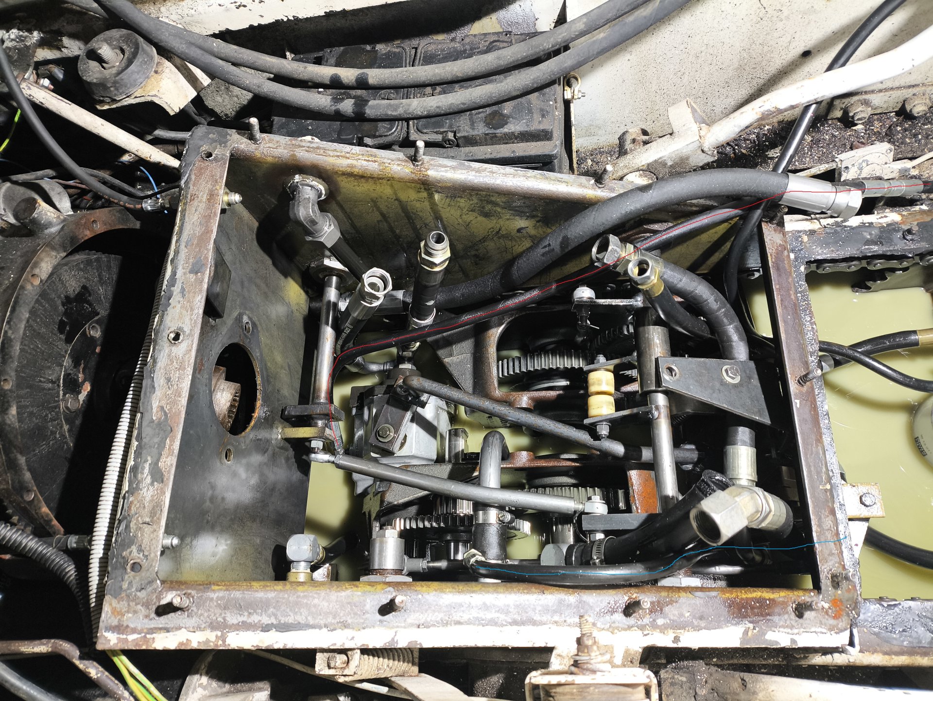
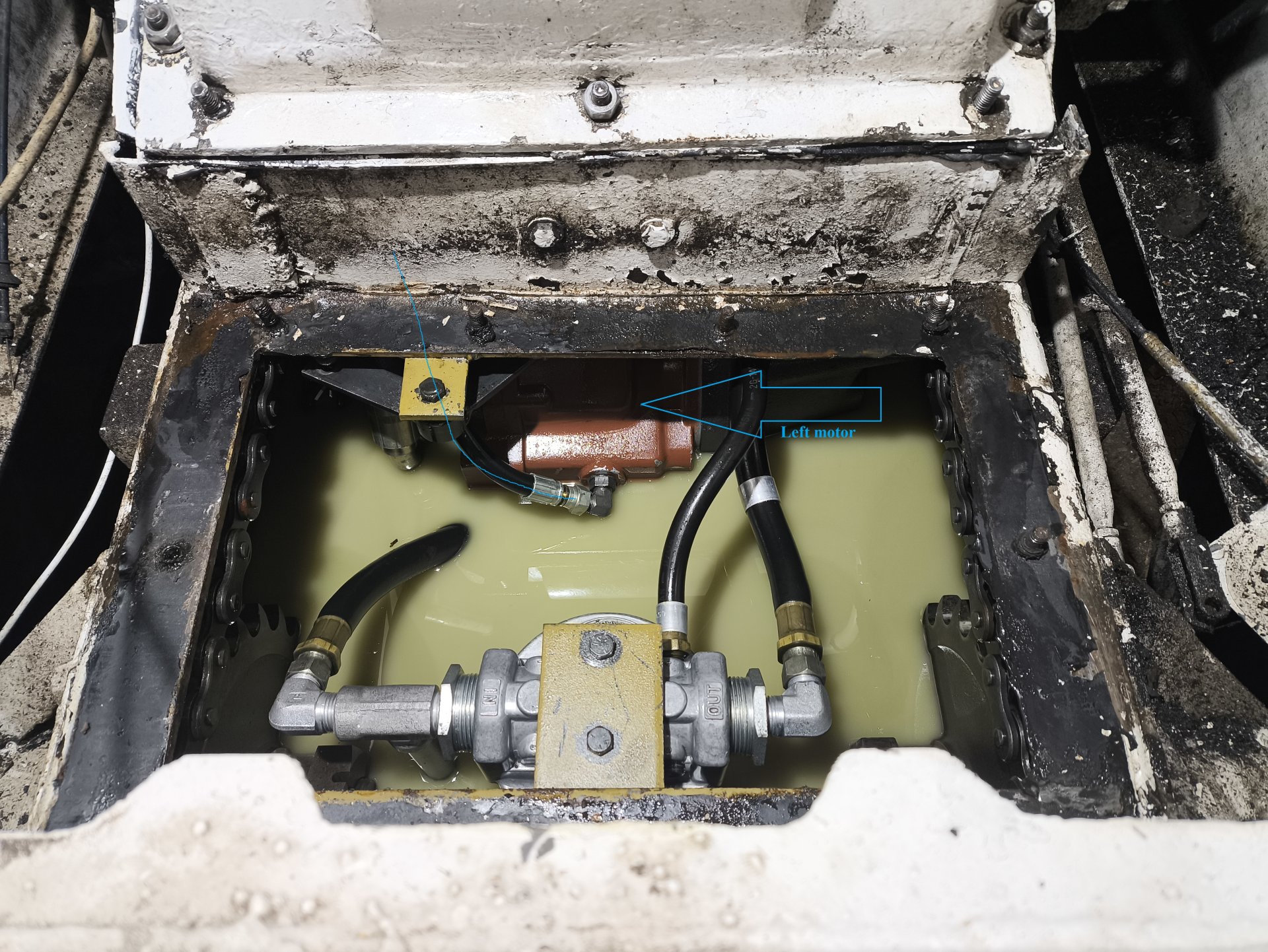
Case drain setup

One thing that really surprised me while inspecting the machine:

  • The case drain of the right hydraulic pump was connected directly to the case drain of the right drive motor.
  • Same setup on the left side: pump case drain connected directly to motor case drain.
This means there was no proper case drain line going to tank. The pump was draining into the motor and the motor into the pump.

This looks completely wrong to me, and I’m concerned how long the machine was operated this way and what damage it may have caused.

I’d appreciate any comments on how critical this is and whether this could explain the symptoms and internal wear.

For the pressure measurements, I disconnected this setup and routed the case drains correctly to tank, according to the hydraulic schematic. I believe this was the correct way to perform the tests.

With the case drains separated, I clearly observed that the right drive motor produces a very large amount of case drain flow exactly at the moment when the right side loses drive.

I also noticed that after correcting the case drain routing, the right side drive seemed to get worse during testing. After a few minutes of diagnosis, the right side had even less ability to move than before, although I can’t say with full certainty if this was a direct cause-and-effect or just coincidence.


One more detail I forgot to mention:

At the very beginning, when I first opened the hydraulic tank / compartment, I noticed that a hose related to the charge pressure circuit was damaged.

I replaced the hose, but the issue appeared to remain unchanged.


Because of this, I suspect internal leakage in the right drive motor, possibly worsened by long-term operation with incorrect case drain routing, but I would really appreciate input from people with more experience.

IMG_20251213_173729.jpg

IMG_20251224_145950.jpg

IMG_20251213_152000.jpg
 
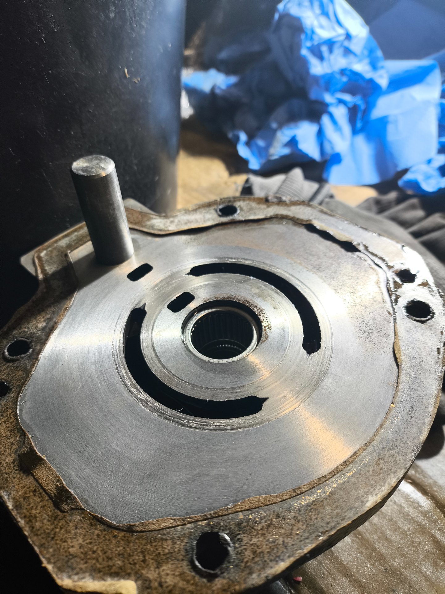
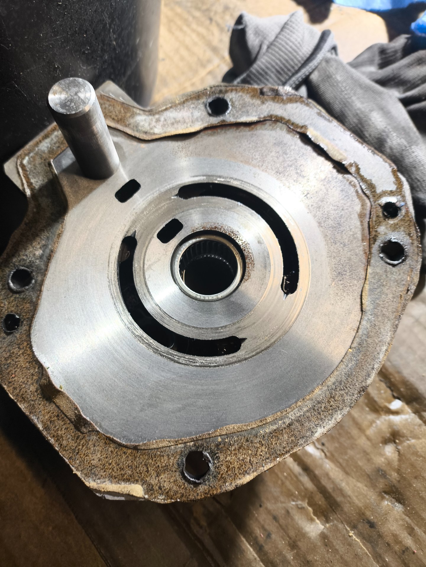
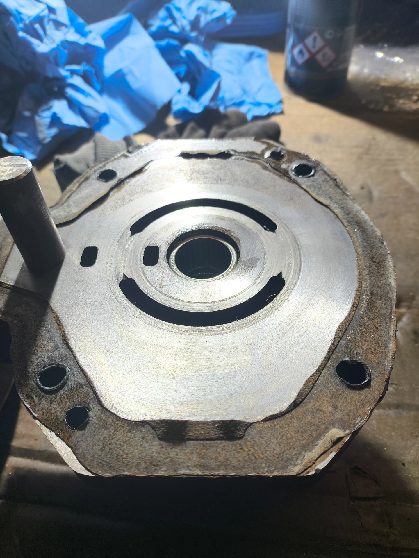
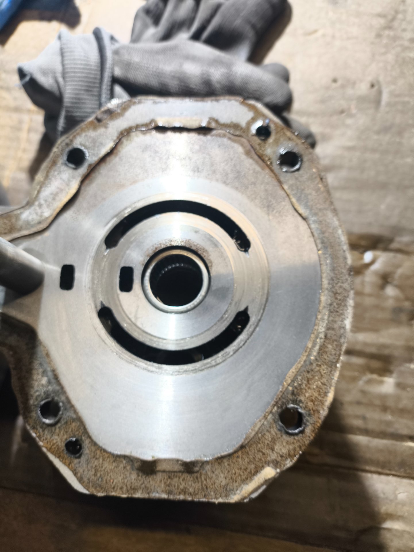
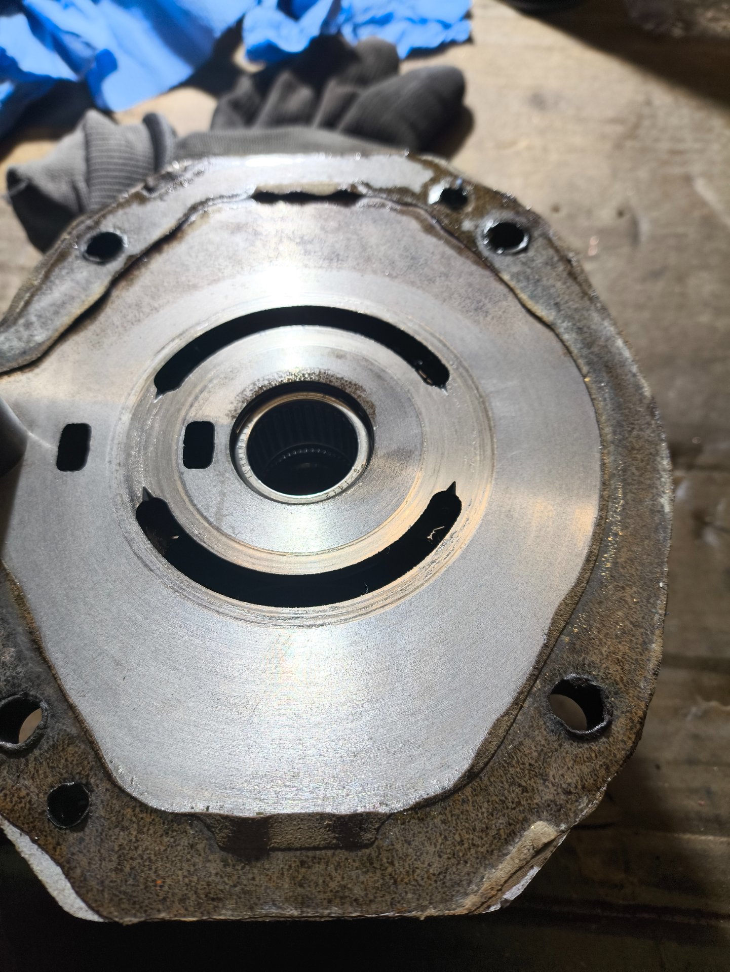
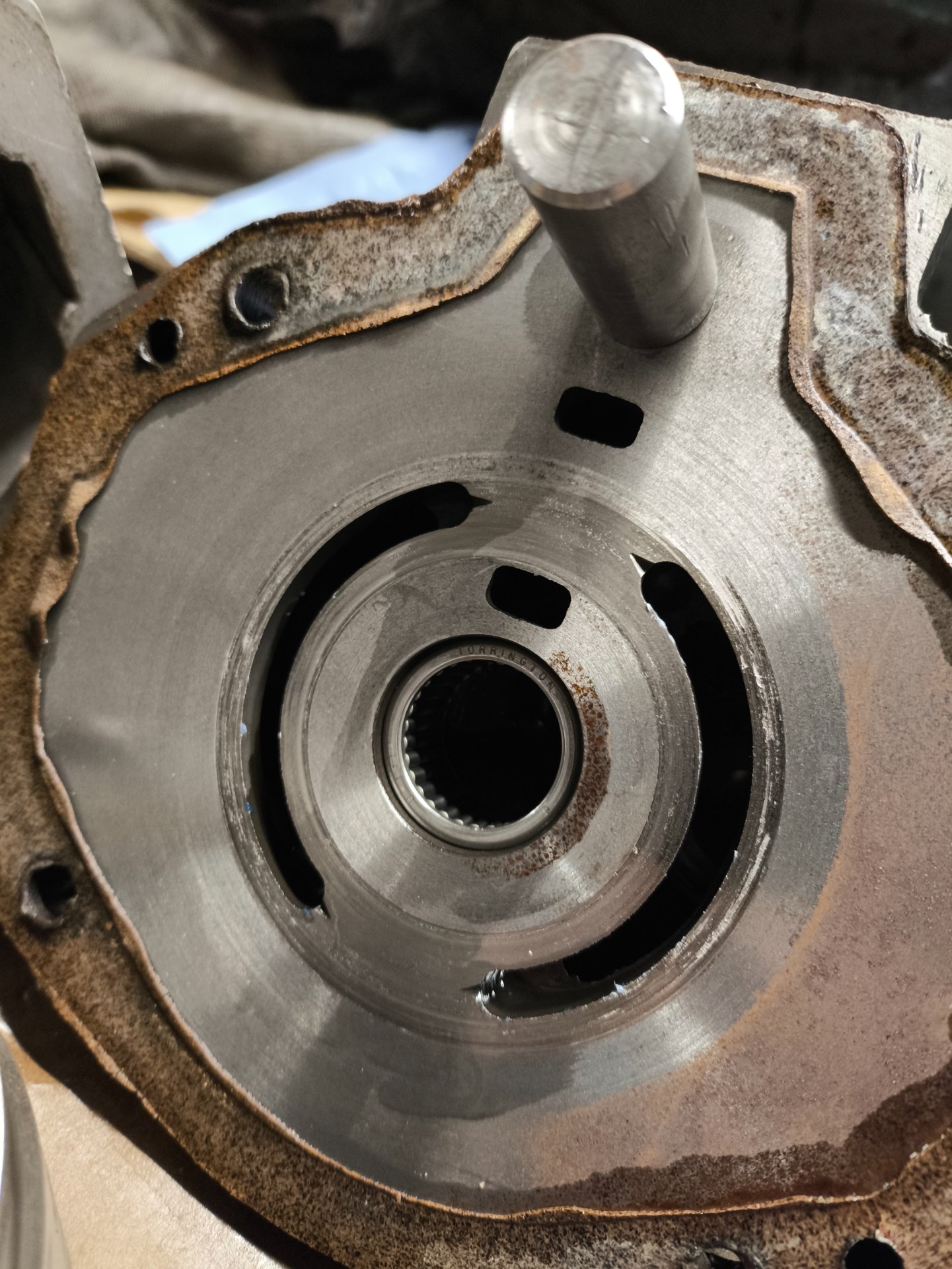
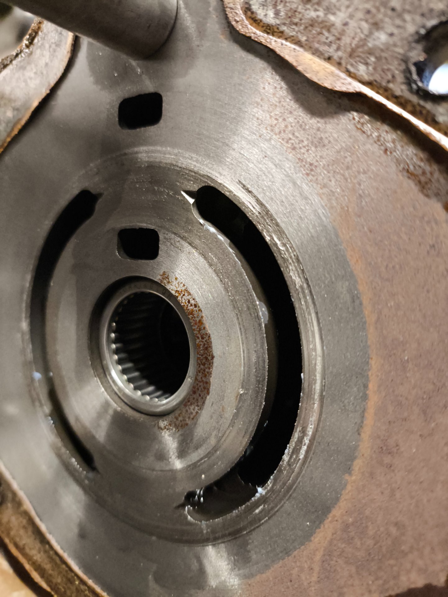
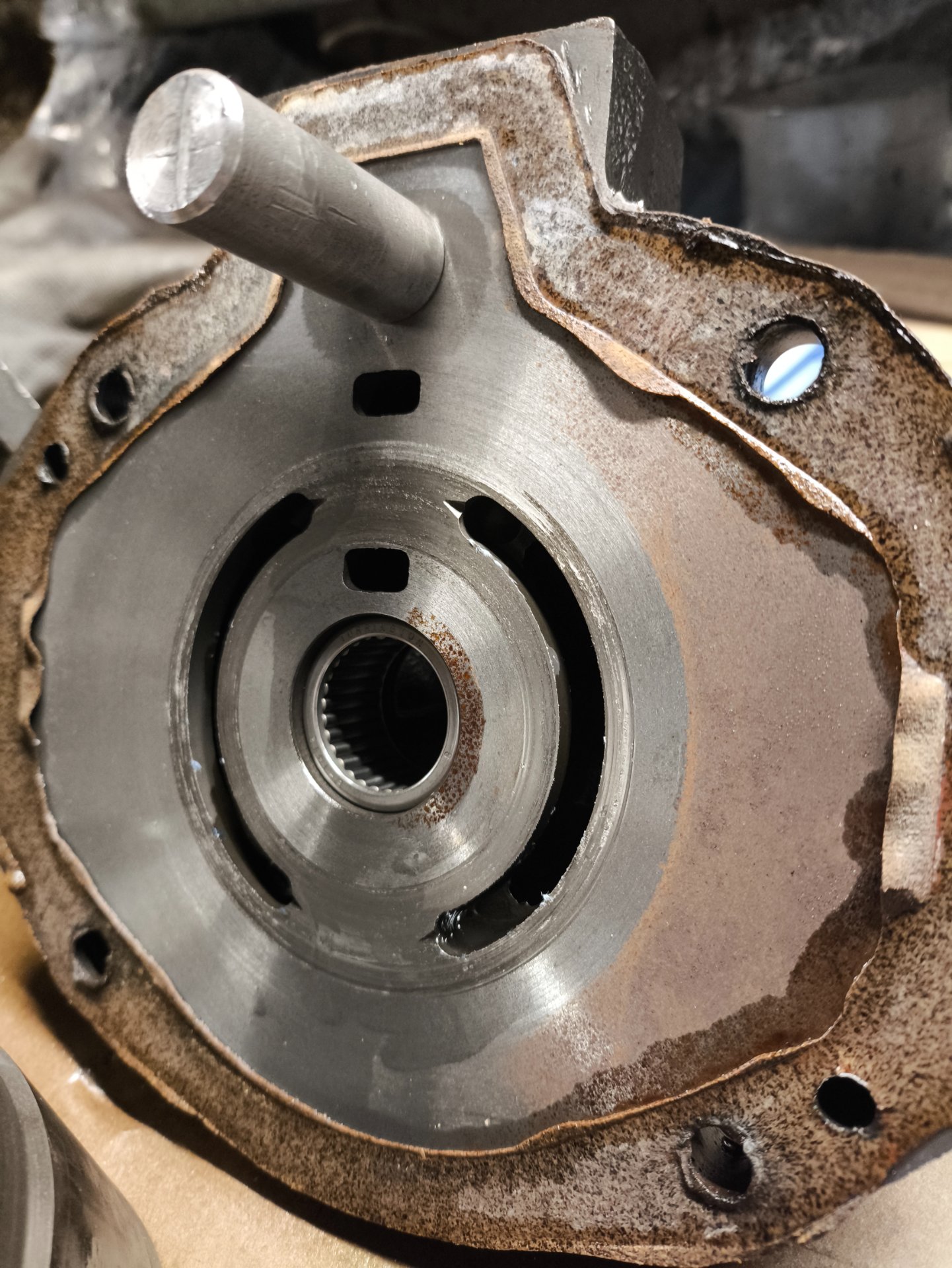
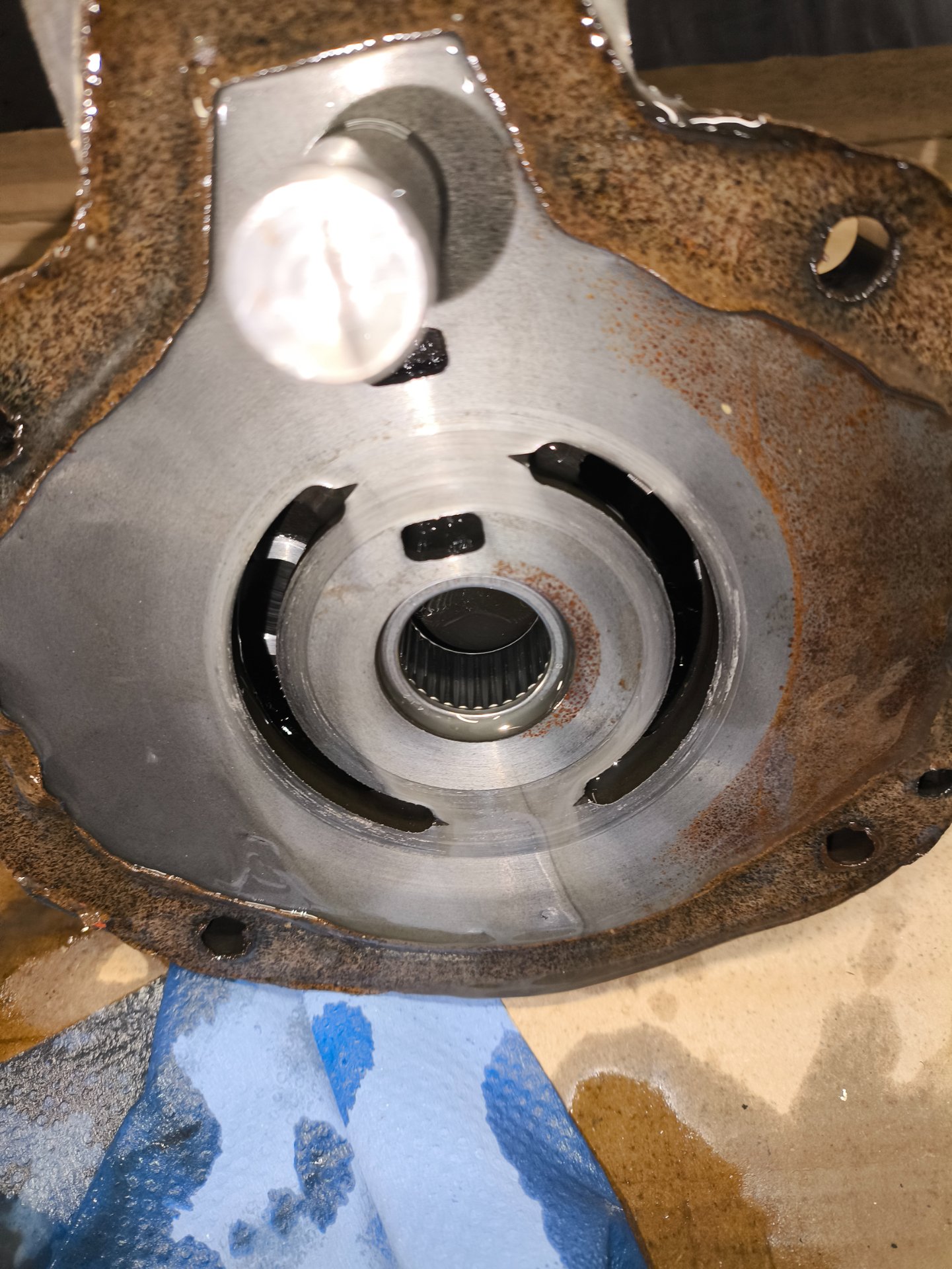
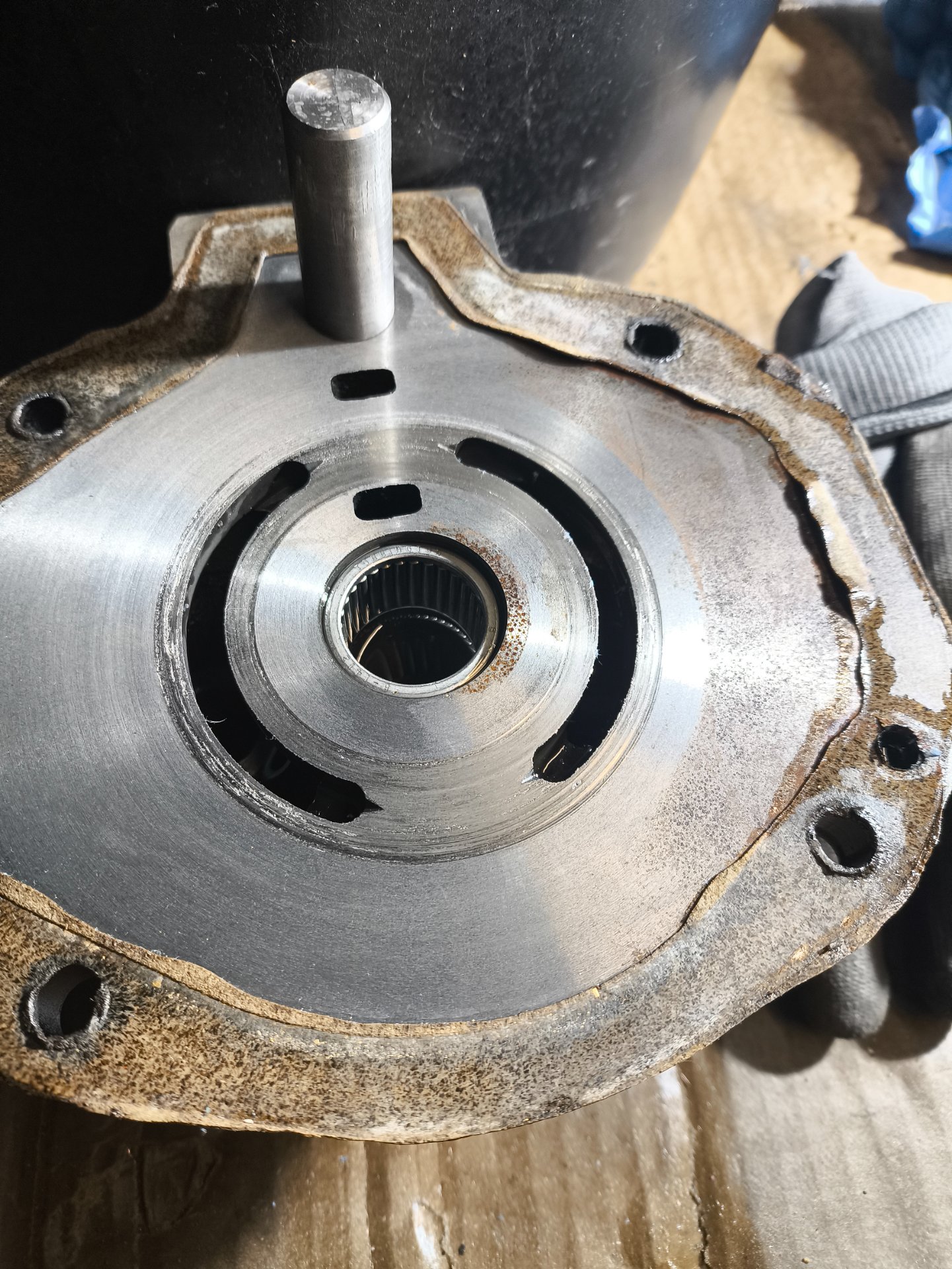
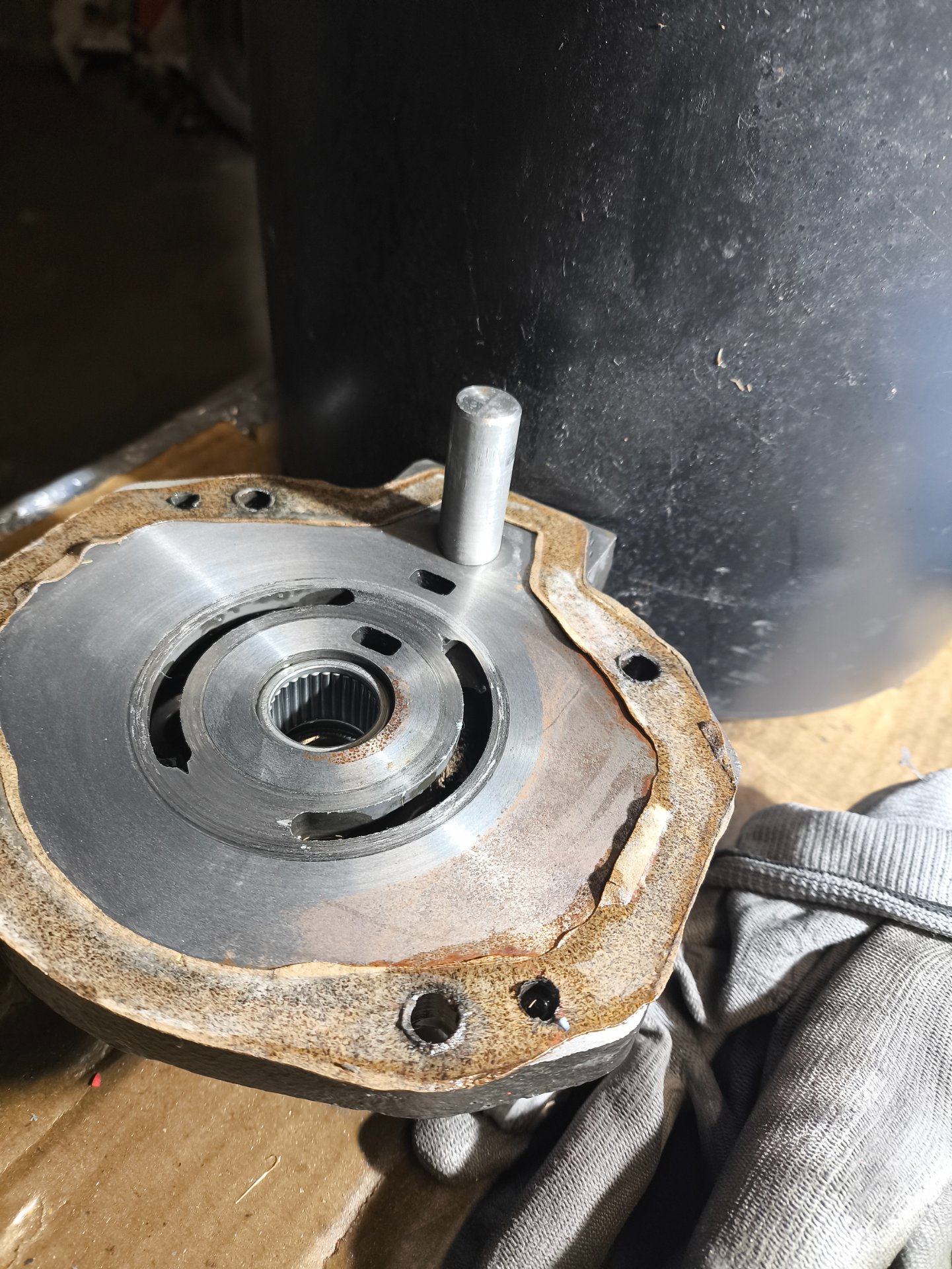
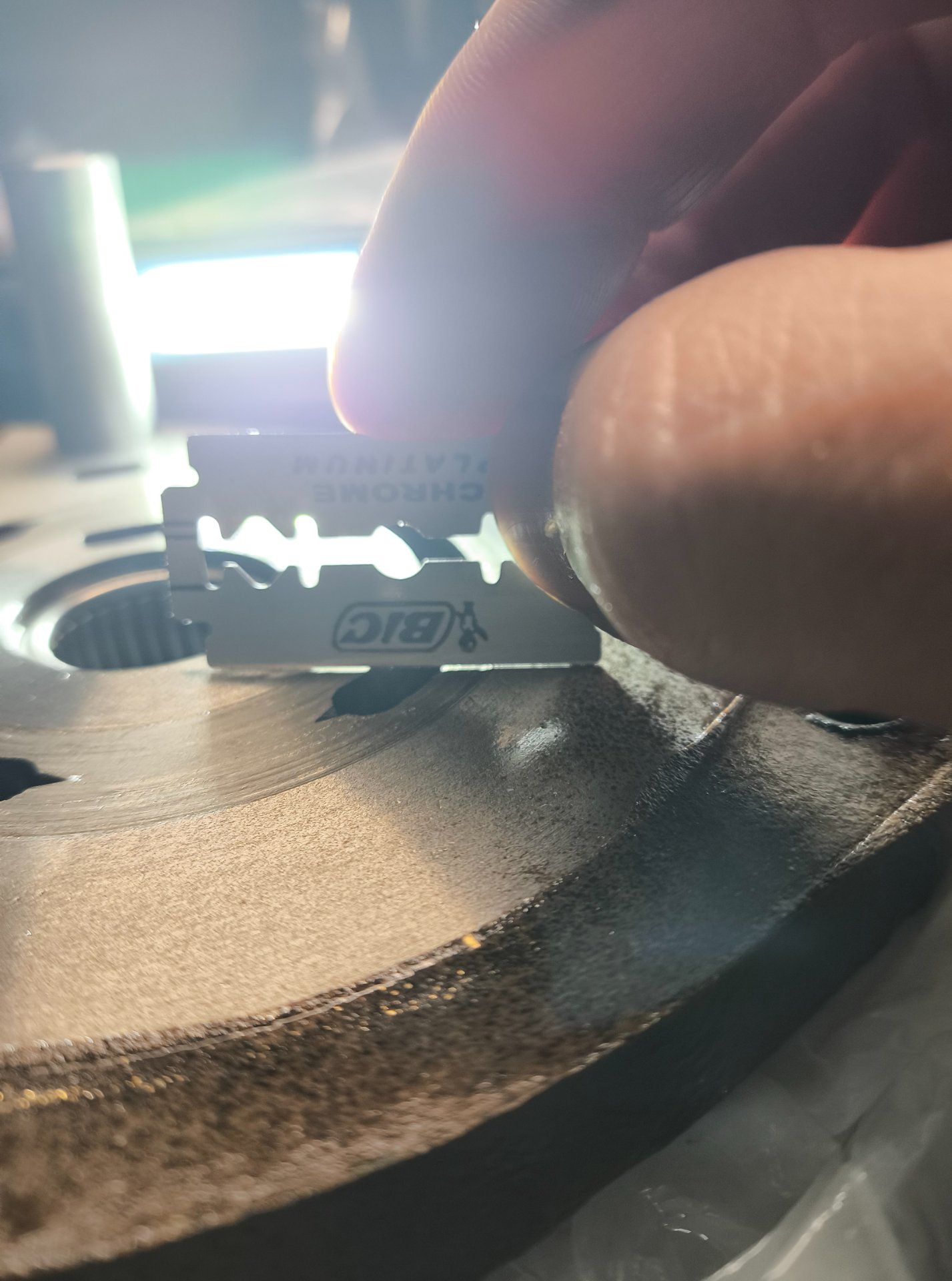
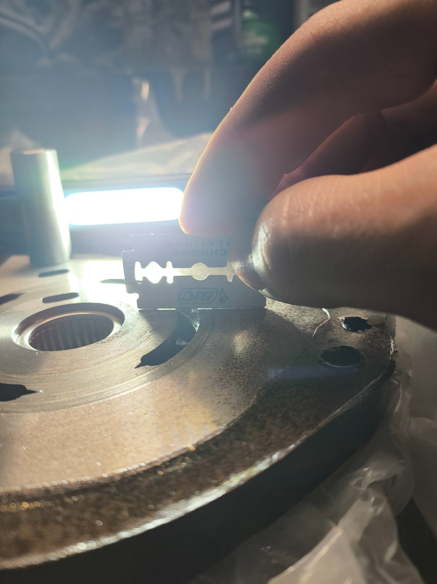
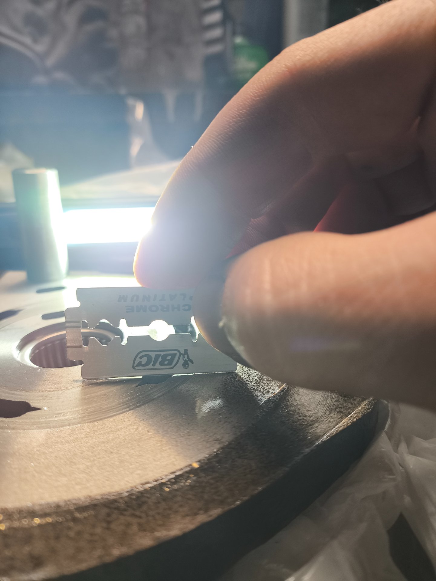
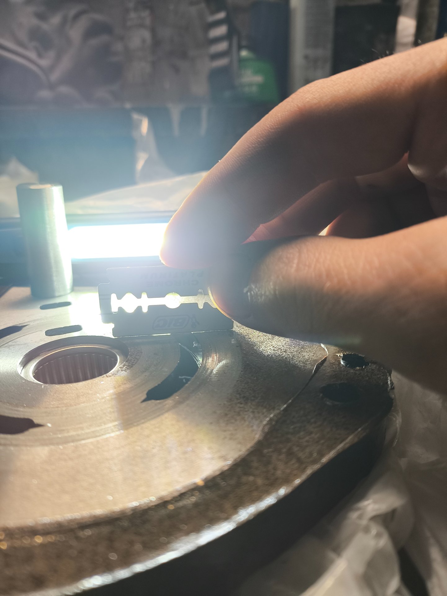
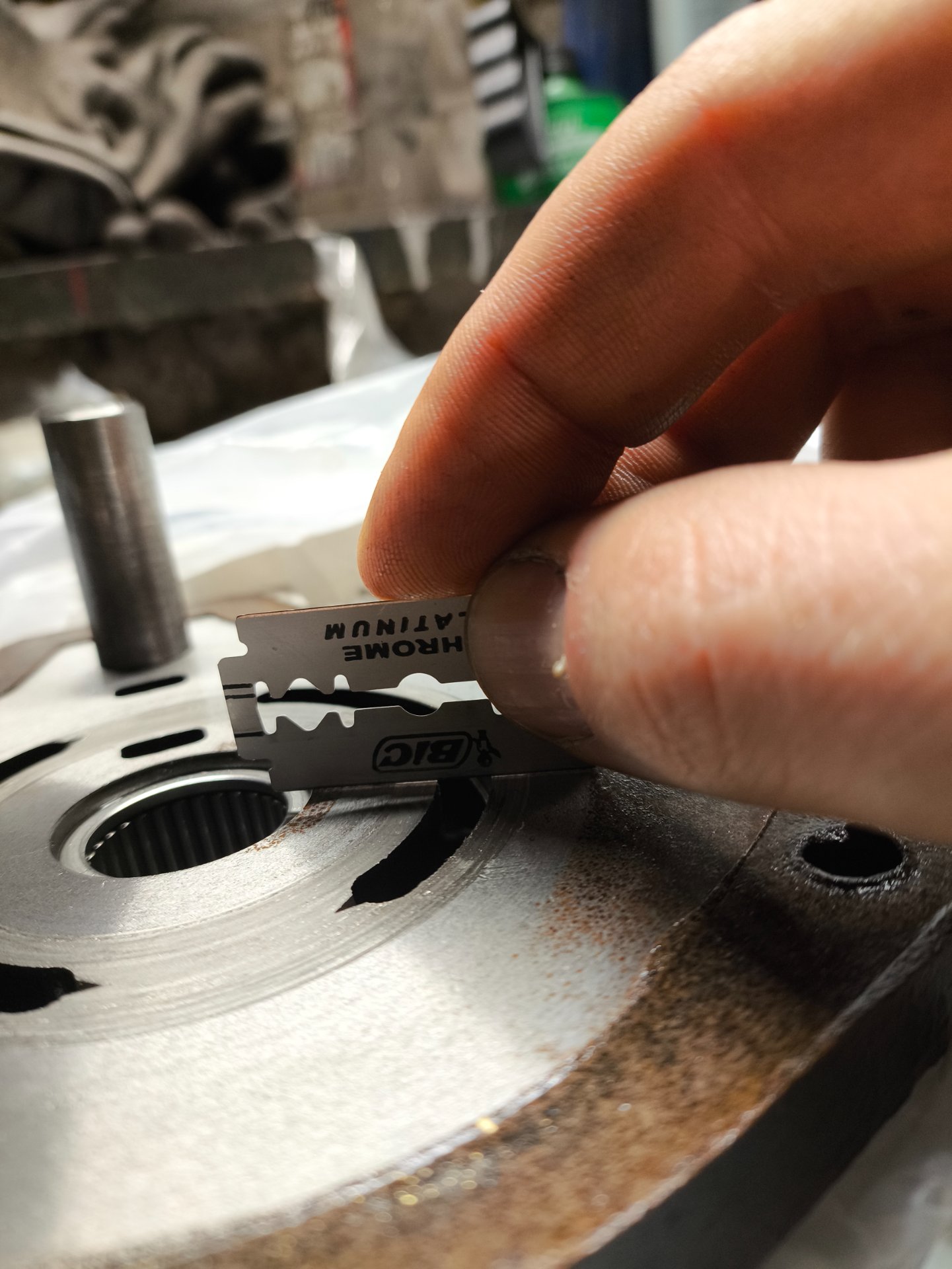
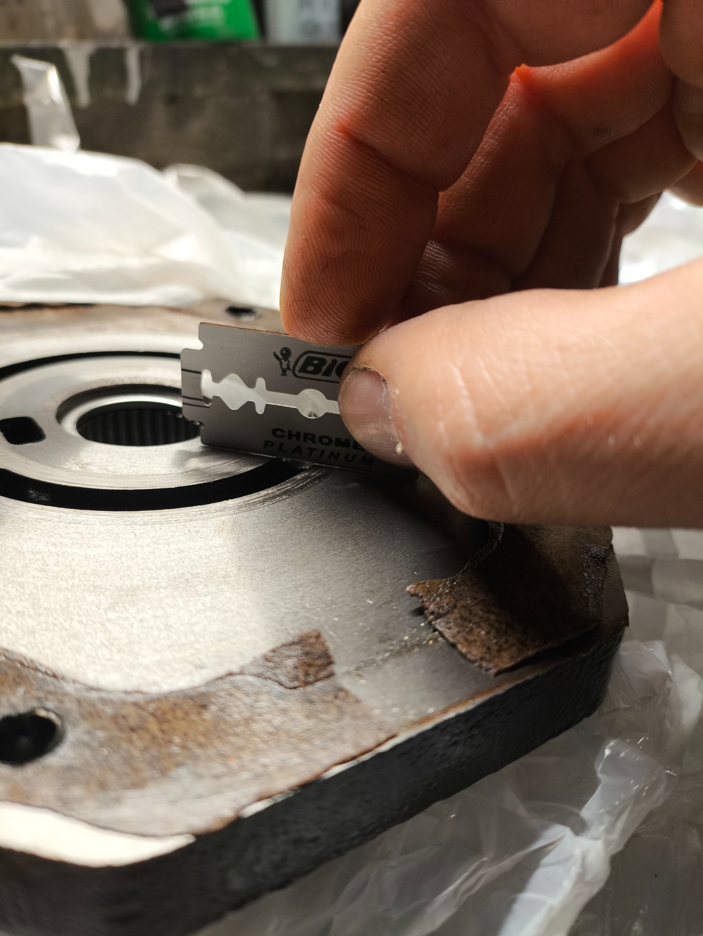
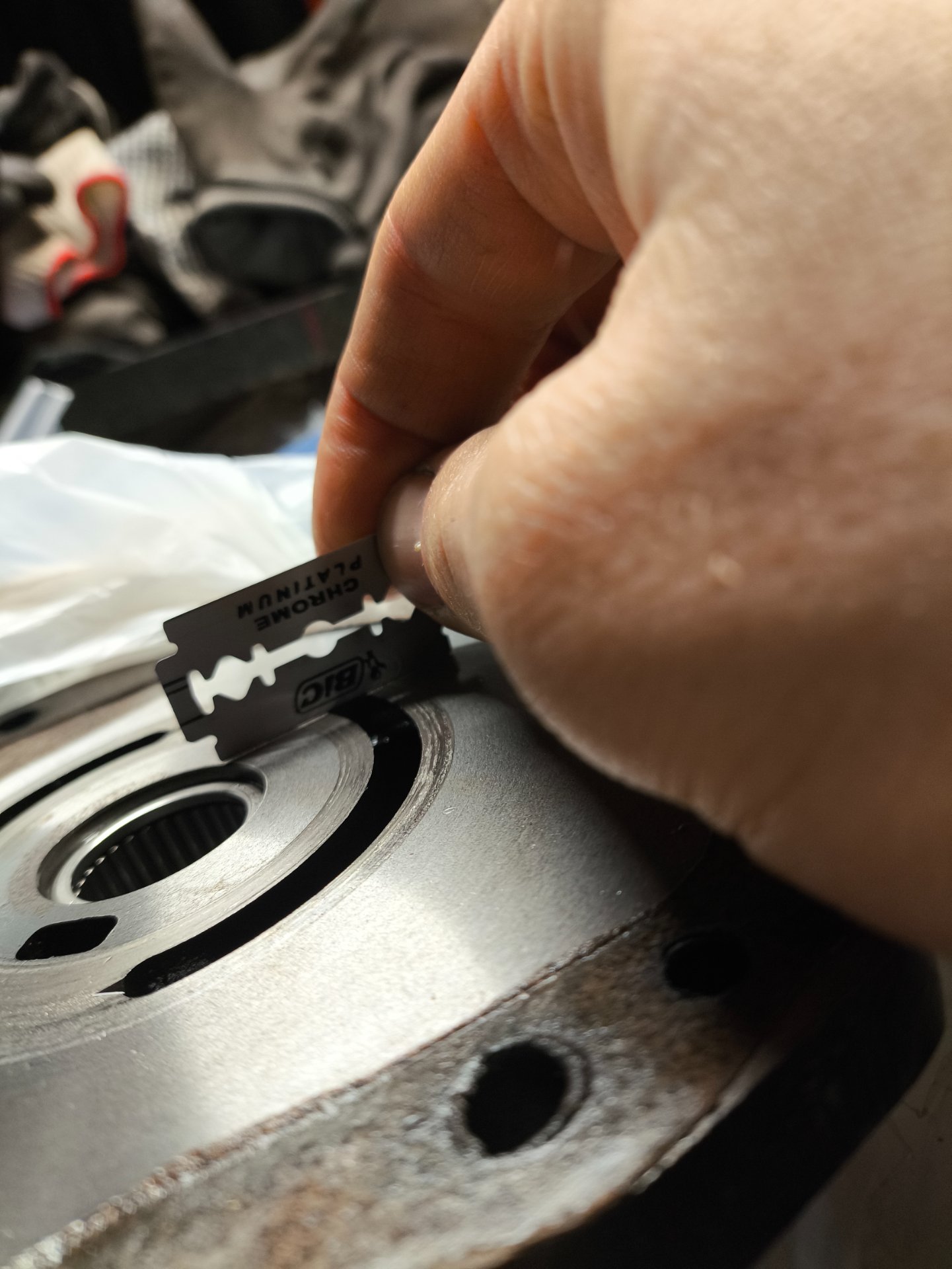
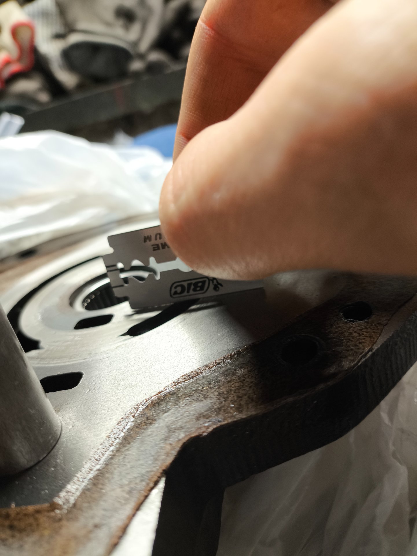
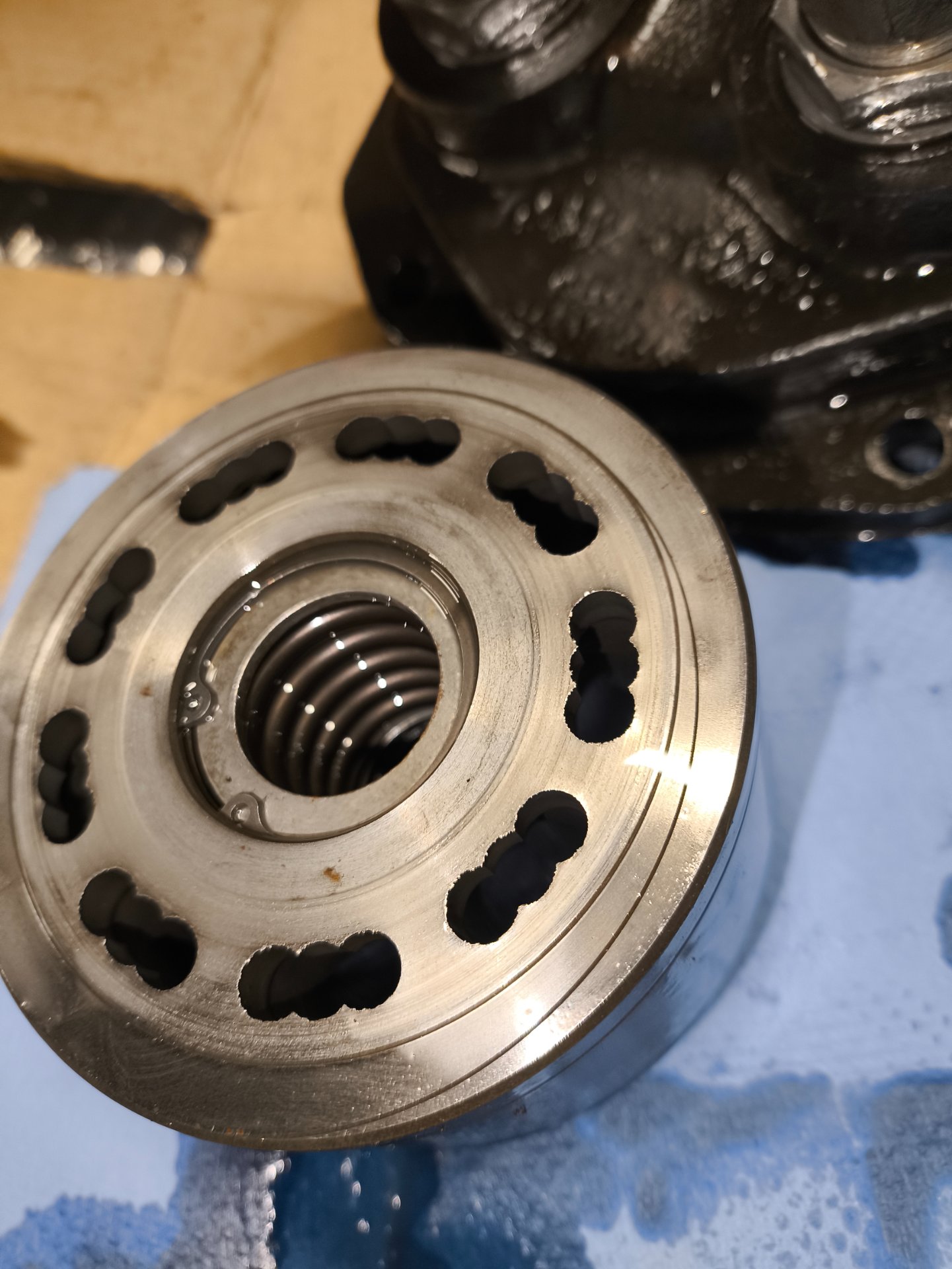
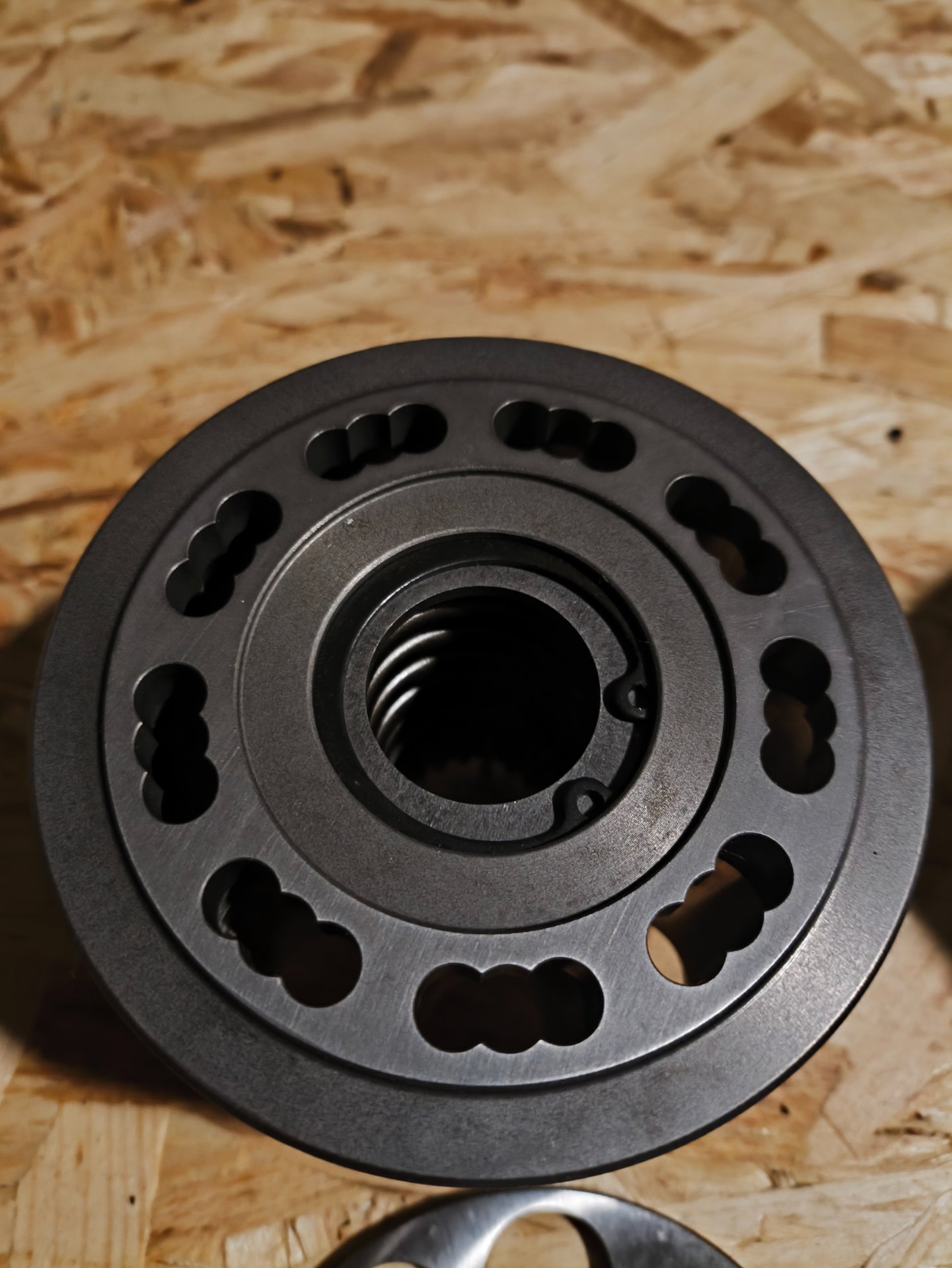
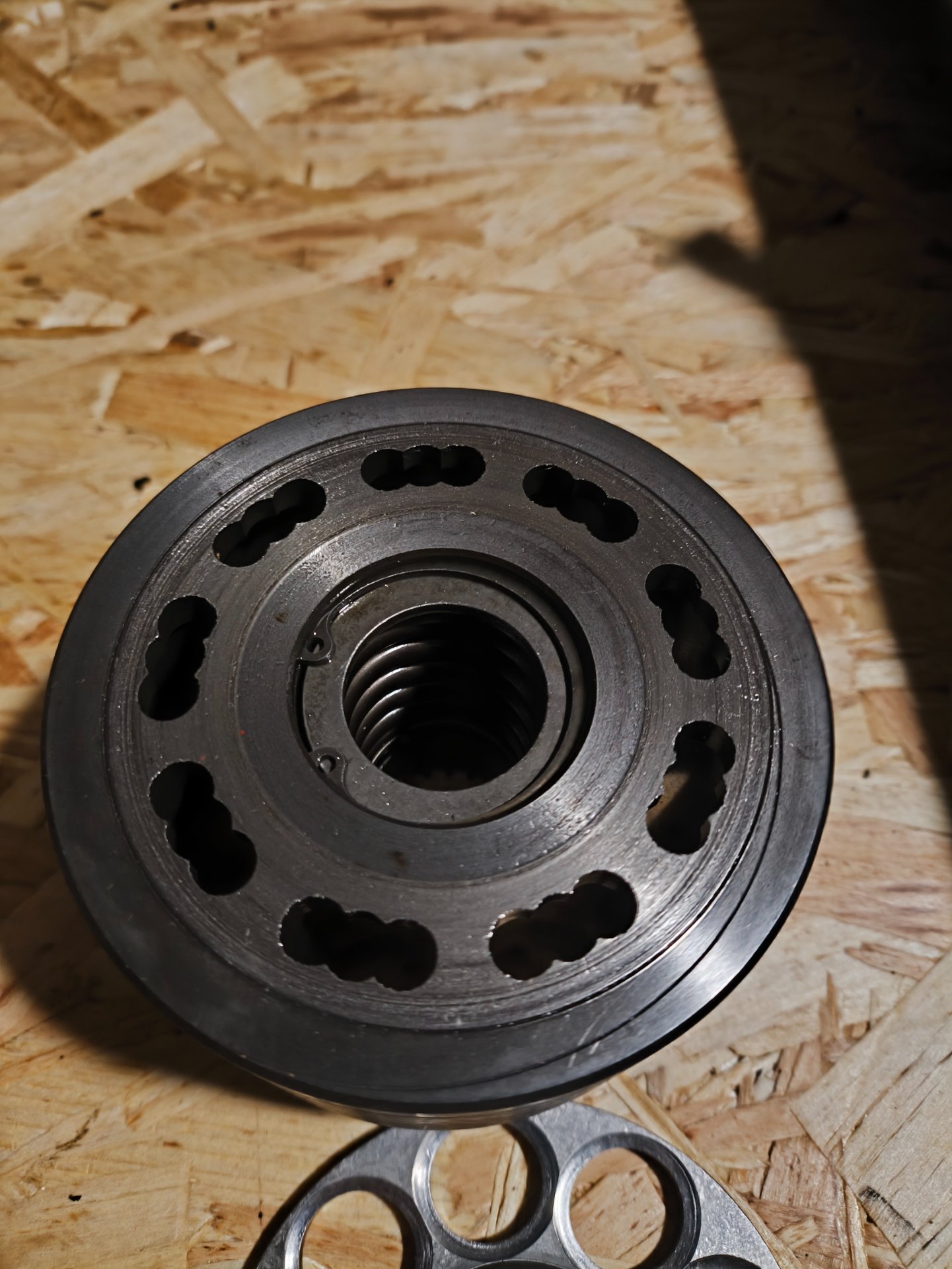
Below are photos of the rear cover from the right drive motor.

I took several pictures from different angles and lighting to better show the wear pattern, surface condition, and any scoring.

My main question is how serious this level of wear actually is.

If I were to leave this rear cover as it is and install new internal components, what kind of consequences should I expect?
 

Attachments

  • IMG_20251228_113704.jpg
    IMG_20251228_113704.jpg
    467.1 KB
  • IMG_20251228_113705.jpg
    IMG_20251228_113705.jpg
    479.1 KB
  • IMG_20251228_113700.jpg
    IMG_20251228_113700.jpg
    445.9 KB
  • IMG_20251228_113658.jpg
    IMG_20251228_113658.jpg
    275.1 KB
  • IMG_20251228_113656.jpg
    IMG_20251228_113656.jpg
    474 KB
  • IMG_20251224_181014.jpg
    IMG_20251224_181014.jpg
    436.8 KB
  • IMG_20251224_181012.jpg
    IMG_20251224_181012.jpg
    340 KB
  • IMG_20251224_181009.jpg
    IMG_20251224_181009.jpg
    457 KB
  • IMG_20251224_173731.jpg
    IMG_20251224_173731.jpg
    544 KB
  • IMG_20251224_173724.jpg
    IMG_20251224_173724.jpg
    428.5 KB
Specifically, I’d like to understand:

  • Would this amount of wear cause excessive internal leakage or loss of efficiency?
  • Could it explain the loss of drive under load and high case drain I’m seeing?
  • Would continued use in this condition risk rapid failure of new parts, or further damage to the pump or motor?
Any feedback on whether this cover is still usable, marginal, or clearly beyond service limits would be greatly appreciated.
 

Attachments

  • IMG_20251228_113712.jpg
    IMG_20251228_113712.jpg
    572.8 KB
  • IMG_20251228_113717.jpg
    IMG_20251228_113717.jpg
    520.2 KB
  • IMG_20251230_111835.jpg
    IMG_20251230_111835.jpg
    258.8 KB
  • IMG_20251230_111842.jpg
    IMG_20251230_111842.jpg
    245.1 KB
  • IMG_20251230_111856.jpg
    IMG_20251230_111856.jpg
    224.9 KB
  • IMG_20251230_111901.jpg
    IMG_20251230_111901.jpg
    231.8 KB
  • IMG_20251230_111950.jpg
    IMG_20251230_111950.jpg
    282.5 KB
  • IMG_20251230_112210.jpg
    IMG_20251230_112210.jpg
    285.6 KB
  • IMG_20251230_112244.jpg
    IMG_20251230_112244.jpg
    256.9 KB
  • IMG_20251230_112310.jpg
    IMG_20251230_112310.jpg
    262.5 KB
You have to look at the entire assembly to make a judgement. Remove that dowel and you could hand lap the entire surface of that housing back to flat, which is how it was originally. The matching parts will also need lapping or surfacing back to flat. The rotor will need attention. Cleaning of debris out of the system, then see what you've improved. I'm sure that not a cheap assembly so it's nothing ventured nothing gained. Some "rebuild" kit might be available to reduce the amount of hand labor or machining needed. Hand lapping will remove the least amount of material. A flat surface plate (kitchen table?) and a sheet of emery cloth of correct grit. Make sure that the correct fluid is in the system and not contaminated. Let us know how it progresses.

That might be air but I think there's water or coolant in there. I don't think air would make it green, unless the oil is green originally. You should try to see if there's an oil cooler leak allowing that. Air will not move much until the pressure gets very high, so if there's friction, the air will have to build up to overcome that. The release upon attaining trigger point will account for the continued movement after the lever is released. That residual pressure can be built up between the lever and the motor.

Look at the drive that's working okay and see how the hydraulics are routed on that. A friendly dealer parts or mechanic might copy a drawing for helping you if you've gotten or are getting parts from them.
 
Last edited:
As an Amazon Associate we earn from qualifying purchases. Product prices and availability are accurate as of the date/time indicated and are subject to change.
Thanks for the detailed reply, I really appreciate you taking the time.

I understand your point that it’s not possible to judge the condition by the rear cover alone. I will post here a little more pictures.

I’ve cleaned the system as thoroughly as possible so far and I’m preparing to run fresh hydraulic oil, as I agree that any diagnostics with contaminated oil would be misleading.

On this machine the oil cooler is a simple air-to-oil radiator, not a water-to-oil cooler, so coolant intrusion through the cooler seems unlikely. My current assumption is that water likely entered through poor sealing of the upper covers over the hydraulic compartment. Or may be just condensation.

I’ve double-checked the hose routing multiple times against the service manual schematics and I’m reasonably confident the routing is correct at this point.

One part that concerns me the most is the lapping process itself, especially on the rear cover – there is no place where to buy it new. I understand how critical flatness is in this area, and while I’m planning to proceed carefully and remove as little material as possible, this will be my first time doing this kind of work on a hydrostatic component. Hopefully I can achieve acceptable results.

Thanks again for the insight — I’ll continue posting updates as I go.
 

Attachments

  • IMG_20260103_141023.jpg
    IMG_20260103_141023.jpg
    604.9 KB
  • IMG_20251226_101550.jpg
    IMG_20251226_101550.jpg
    417.5 KB
  • IMG_20251226_101553.jpg
    IMG_20251226_101553.jpg
    399.2 KB
  • IMG_20251224_173704.jpg
    IMG_20251224_173704.jpg
    297 KB
  • IMG_20251224_181256.jpg
    IMG_20251224_181256.jpg
    365.6 KB
  • IMG_20251224_181540.jpg
    IMG_20251224_181540.jpg
    254 KB
  • IMG_20251225_102940.jpg
    IMG_20251225_102940.jpg
    515.5 KB
IMG_20251228_113710.jpg

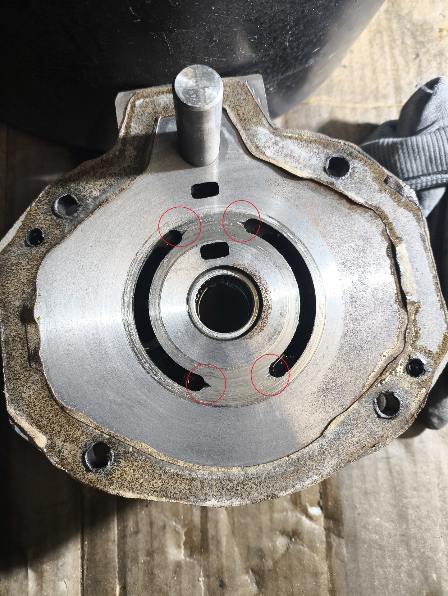
I have one more question regarding the rear cover lapping process, and I’ve attached a photo with the areas marked.


If during hand lapping it turns out that a significant amount of material needs to be removed to restore flatness — or if light machining followed by lapping would even be considered — I’m concerned about the effect this would have on the small triangular reliefs / pockets around the ports (marked in red).

As far as I understand, these features are not accidental and may play a role in flow transition, pressure relief, or cavitation control at the port edges.

My question is:
How critical is it to preserve the original shape and depth of these reliefs?

If lapping or resurfacing significantly alters them, could that:
  • negatively affect port timing or flow characteristics?
  • increase the risk of cavitation or noise?
  • reduce efficiency or shorten service life?

In other words, is there a practical limit where restoring flatness starts to do more harm than good because these features are no longer within their intended geometry?
 
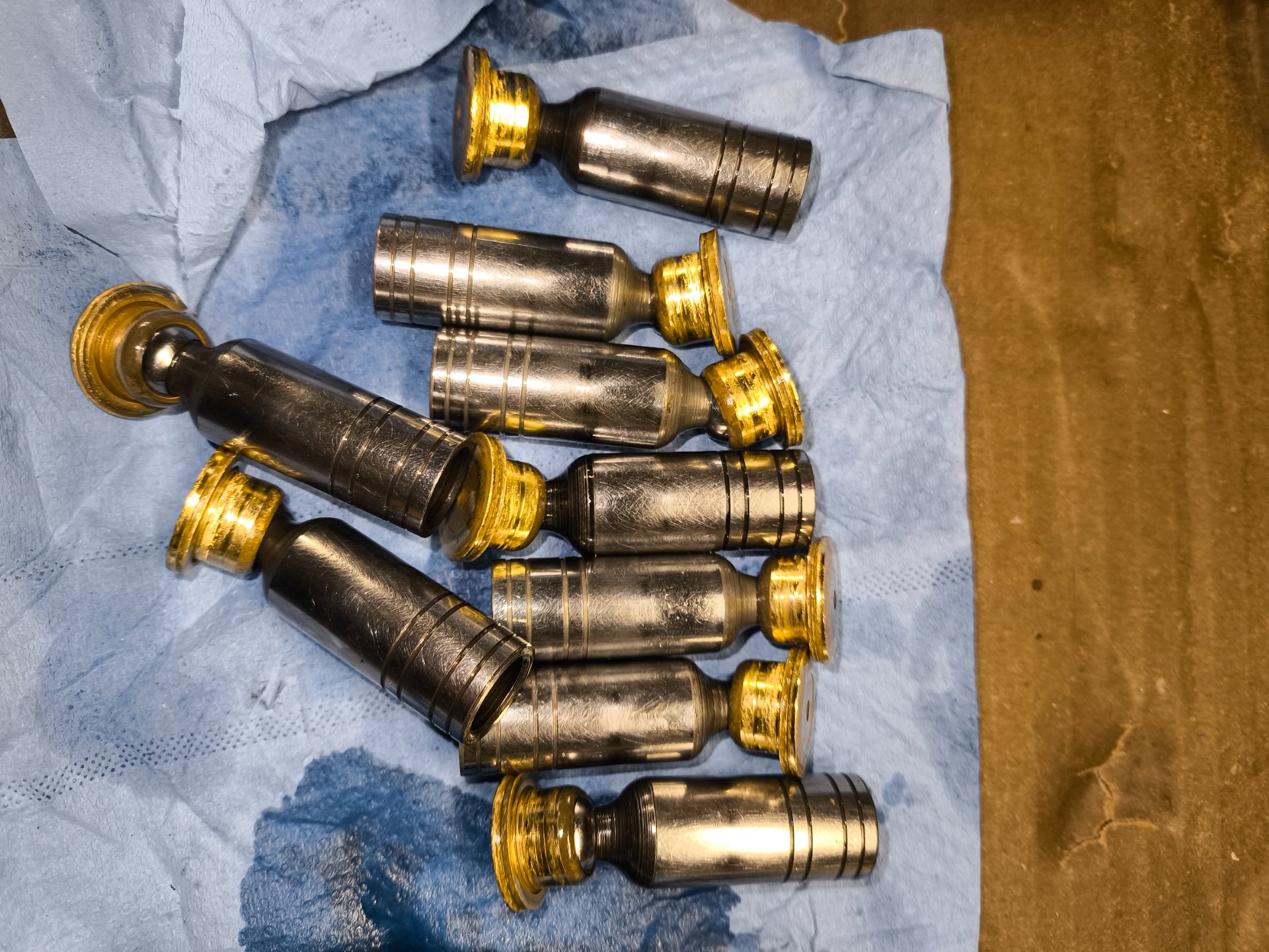
Those little reliefs are just for a bit of oil to get dragged under the contact part of the pistons. Pistons appear to be brass tipped. I'm not sure what the shape of those were to begin. I'm guessing they were flat. The pistons need to be examined carefully and probably some hand lapping done to them. The little "V' grooves" can be filed with a 3 sided file if you need to reprofile them a little. I doubt that it's anything critical. It appears the pistons stopped sliding because of the oil contamination and began digging in. That probably caused the scoring. The sides of the pistons need to be polished a bit so they move freely in the cylinder barrels. Terminology may not be perfect but that's what I will call it. There has to be some clearance for the oil to get around them and lube, so the sealing is not so critical, in my opinion. They should also rotate freely as that spreads or prevent wearing. I had experience with a hydraulic drive motor that had solid pins driving the waffle plate. The ends of the pins had been damaged somehow due to the pressure and they were convex on the driving end. There were cracks and broken pieces missing. I just ground them off in the lathe, got them to as close a shape as I could to the waffle plate concave groove and then hand polished to the final shape. They were never worked on again and lasted over 10 years. They were obviously a few millimeters shorter, but it didn't make a difference. Nothing ventured nothing gained. If it's already broke, you can't hurt it......much. That hydraulic motor was a direct drive to turn a 4500 lbs printing cylinder in a processing machine. Lucky I guess. I've also hand lapped Porsche SOHC lifters with 176.000 miles that had a slight swirl to them. I don't remember the grit but my company had all numbers and they polished easily on the break room table. They were about twice as wide as American lifters so the pressure was spread better and the cam lobes were wider. Everything in the hydraulic system is oil submerged so clearances can be a little bigger than original. What can you do? Let us know how it progresses. An 8 x 11 sheet of emery paper should do nicely. That plate looks cast iron or steel so should clean up fairly easily. Use some hydraulic oil to let the polishing residue wash out.

Great pictures with correct detail displayed for examination.

Good luck to you.
 
Thanks for taking the time to share your experience, I really appreciate it.


After giving it some thought, I decided to look for someone with proper lapping equipment and experience. I managed to find a specialist who has a dedicated lapping machine. I showed him the rear cover, and his initial opinion was that the scoring does not look too severe and there’s a good chance it can be successfully lapped.


I’ve left the cover with him and I’m waiting for the results now. Once it’s done, I’ll take photos and share an update here.
 
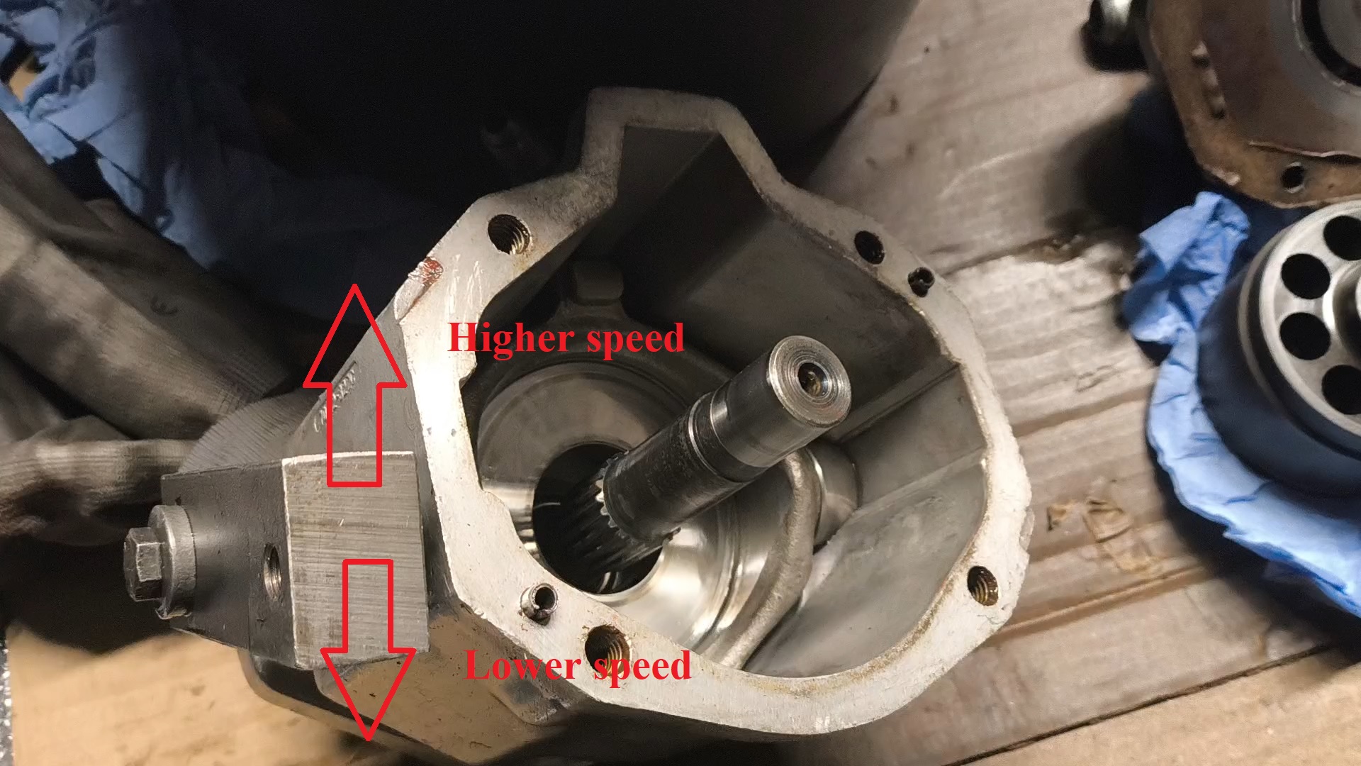
I have a question about how motor speed relates to swash plate angle on this hydrostatic drive. I’ve attached a photo and a short video to show what I mean.


Based on my understanding, a larger swash plate angle corresponds to lower motor speed and higher torque, while a smaller swash plate angle (closer to neutral) corresponds to higher motor speed and lower torque, assuming the same input flow.
speed.jpg


In the attached photo, I marked what I believe should be the low-speed / high-displacement position and the high-speed / low-displacement position. Please correct me if my understanding is wrong.


The reason I want to clarify this is that the entire linkage system on this machine is very worn. There is significant play in the linkages — in some places measured in centimeters.


Because of this, my current plan (at least temporarily) is to lock both drive motors in the low-speed position, which should provide more torque and reduce stress on the system. I would avoid using the speed selector lever entirely. For reference, the speed selector lever itself appears to have been partially cut off by a previous owner.


Before doing this, I’d like to confirm that my understanding of the swash plate angle vs speed relationship is correct.
 

Attachments

  • speed.mp4
    speed.mp4
    9.8 MB
Wow where to start, the pice that you have the razor blade showing light under it MUST be perfectly flat and it's mating part so oil dosent get under the plate compressing the spring in the rotating assembly think of it as starting to hydroplane dumping oil to the least resitance ie case drain, the pistons in the rotating assembly tollarence is so tight that the oil is the seal between the pistons and assembly too much clearence and you generate a lot of excess heat, the motoer are connected to the wheels and the pumps connect to the engine, are we looking at the pump or motor? if the pump the swash moves past netural to direct oil to foward or backwards, 2 speed motors just change the angle of the swash more angle, more angle the more oil needed to fill the cylinder , on the pump little movment moves little oil allowing much higher pressure with out draging down the engine speed, I would be looking to see if you can find a scrap yard that has parts, there used to be a place in Iowa that parts scrapped skid steers and you could maybe get a good used part. I never had a BC apart I have done several New Holland pump just lapping the bronz lenz, the proces was a flat pice of glass and 400 0r 800 grit paper , wd 40 between the paper and glass to hold paper in place lay wet top of paper lay your pice to lap and move in figure 8 twice rotate the pice 1/4 turn repeatr figure 8 until you have a compleate rotation then check repeat several times as necessary other wise you need a lapping machine as the tollarence between the 2 mating surfaces will allow the hydroplaning effect if too far out of wack, I don't know what that is 1/2 thousands? or 1 ten thousands?
 
Last edited:
Thank you very much for taking the time to explain all of this — I really appreciate it.

To clarify, we are looking at the motor, not the pump. And yes, your explanation confirms what I understood: on the motor, a larger swash angle means larger displacement, more torque and lower speed.

Regarding used parts — unfortunately in Europe it has been very difficult. I have not been able to find a single used hydraulic motor for this application anywhere in Europe, and even if one appeared, there is always the question of its internal condition and wear.

At the moment I have already given the motor end cover to a machinist who agreed to lap it. He has a lapping machine. I spoke with him today and he said he will first measure the depth of the scoring before starting. I am aware that if too much material has to be removed, surface hardness could become an issue, and that is something I do not yet have a good solution for. For now, I am hoping that only minimal material removal will be required.

Thanks again for sharing your experience — it has been very helpful.
 
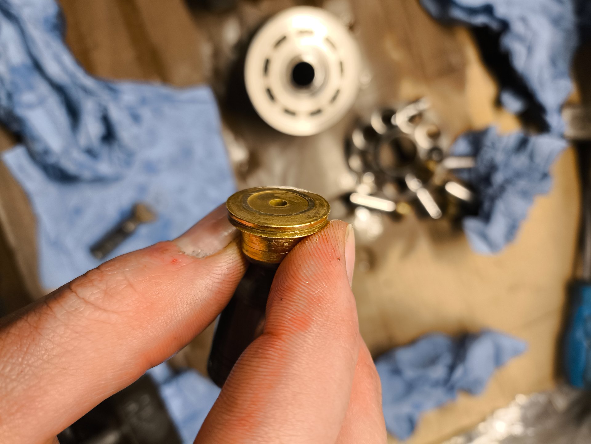
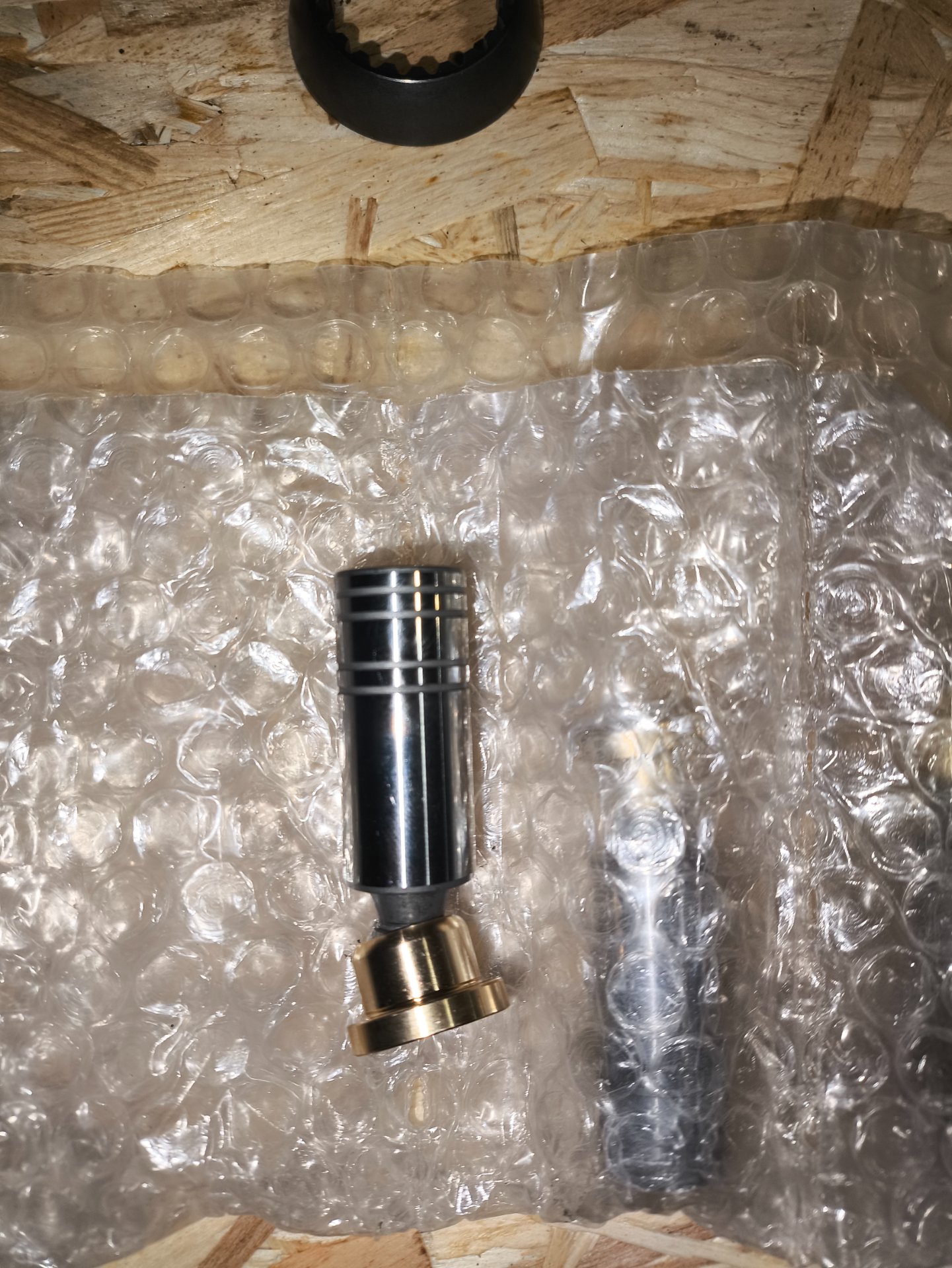
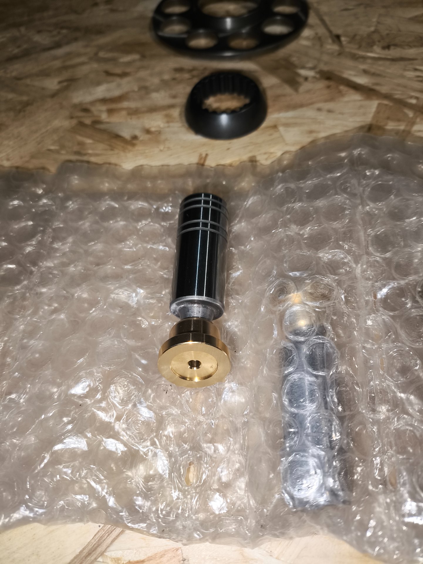
Considering the lenz is bronz I don't think hardness will be an issue, remember soft material holds grit and acts to wear hard materials, the grove in the lenz I believe was put there to bleed off excess oil so the plate doesn't lift as easy and when it is lapped down I would suspect that it will still need to be there for such purposes, the little sbronz slipper feet on the pistions you pictured between your fingers just need to be polished up so they dont shed any debri.
 
Last edited:
Thanks for the reply.

Just to clarify, on my motor the end cover is steel and the cylinder block is also steel — there is no bronze lens in this design.
The end cover itself is the valve/distribution plate.

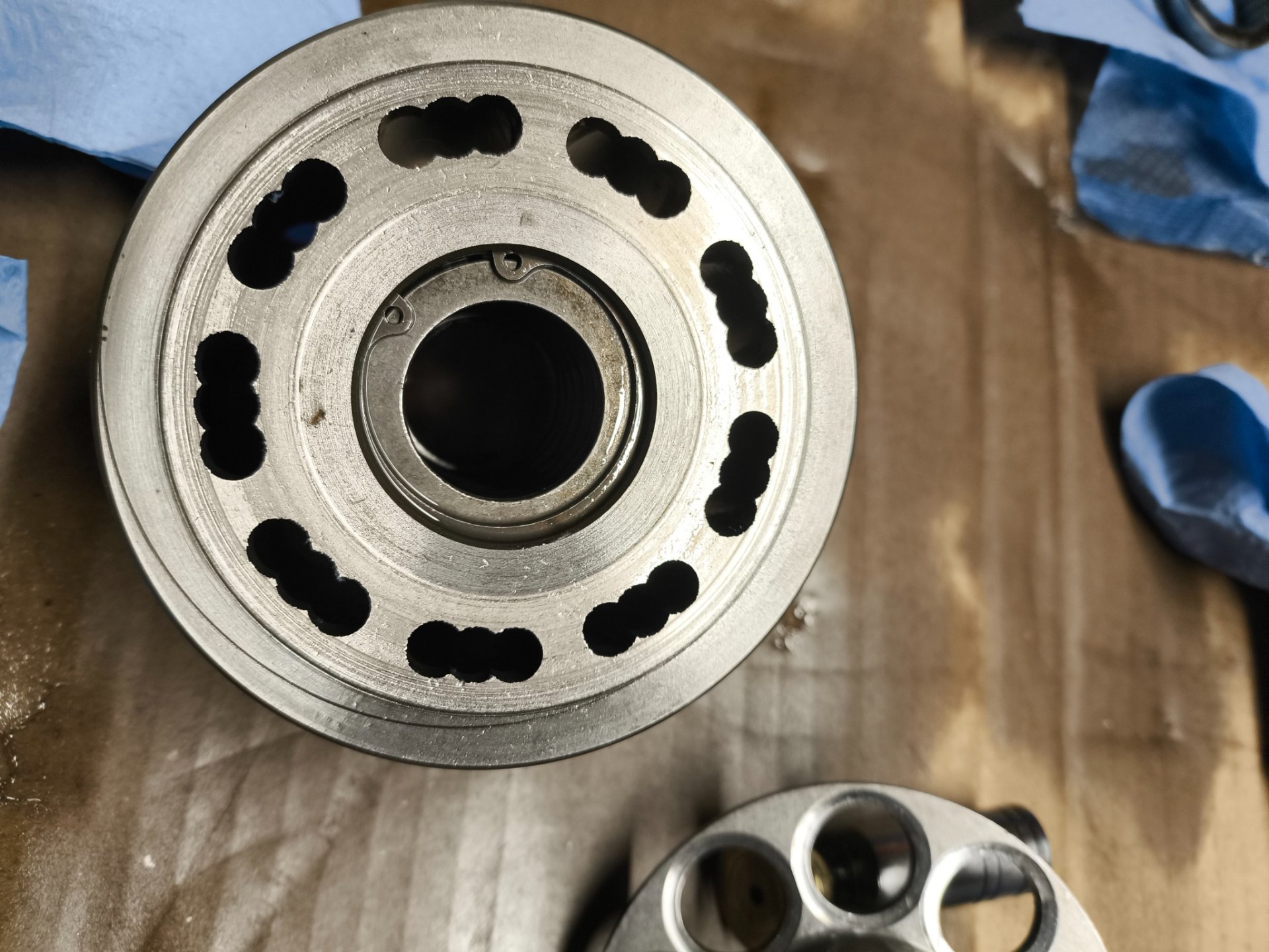
Here is some photos of the parts.

IMG_20251228_113656.jpg


Thanks again.
IMG_20251224_181306 (1).jpg

1768025841508.png
 
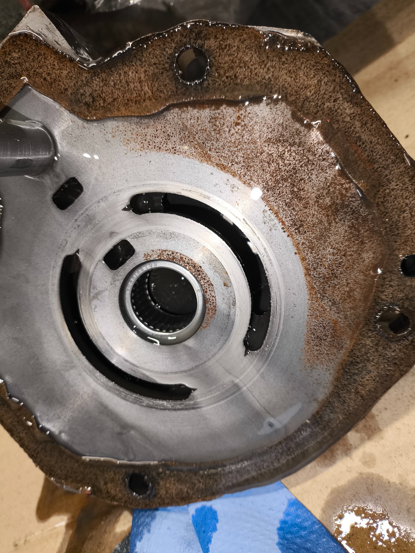
Quick update on the progress.


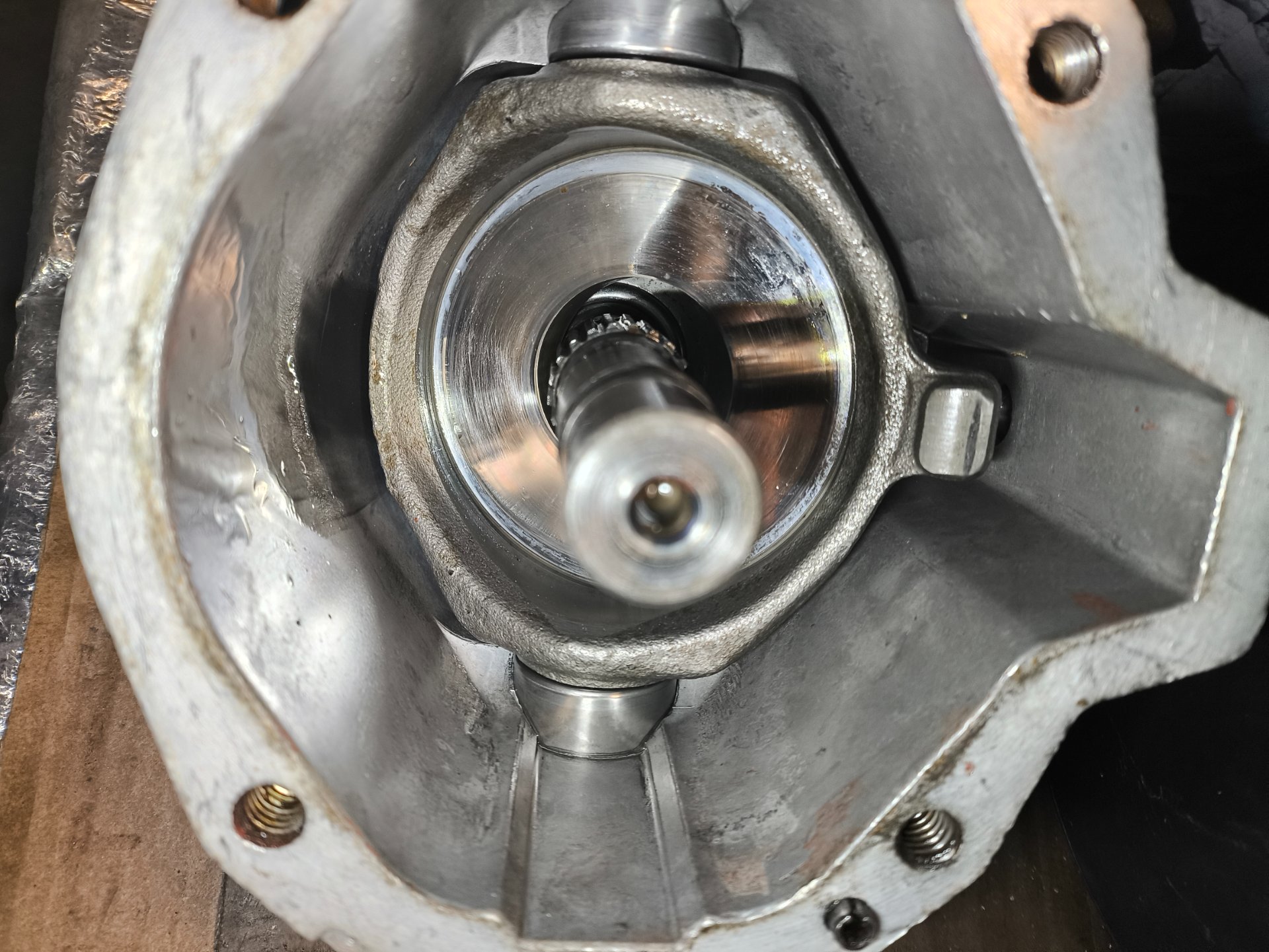
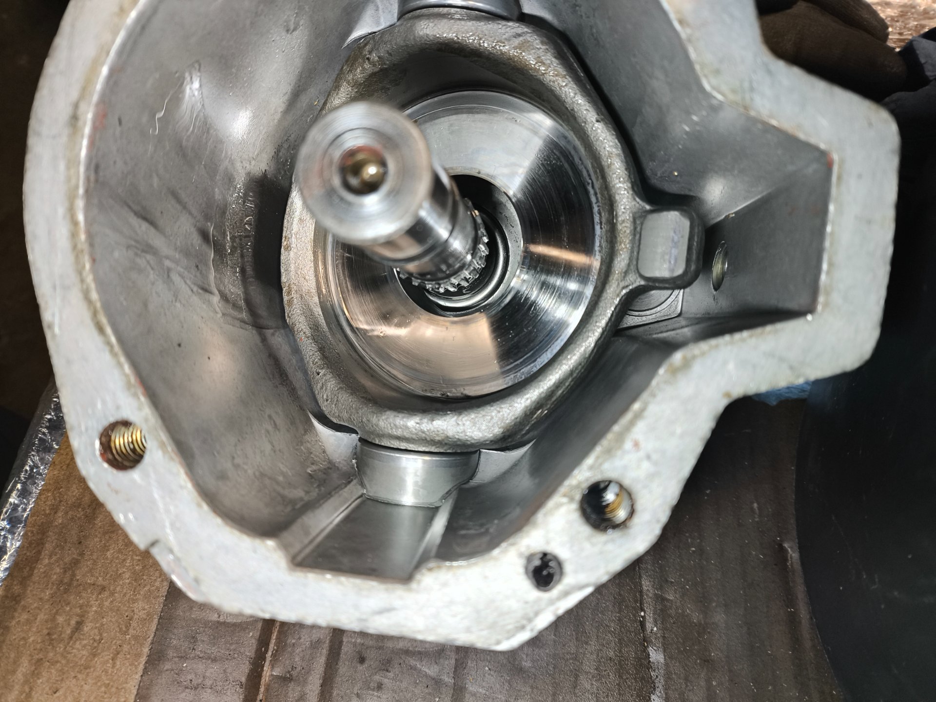
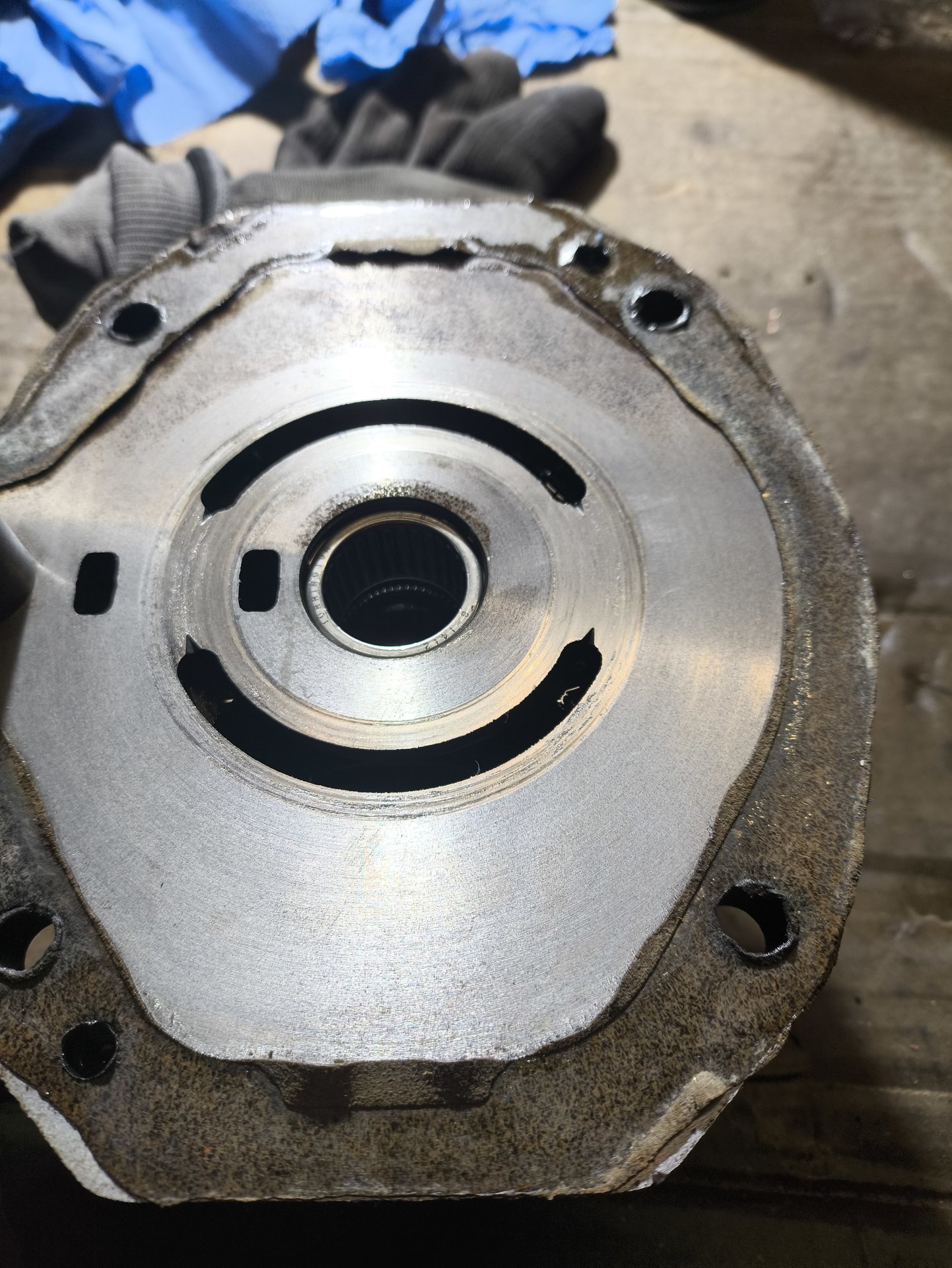
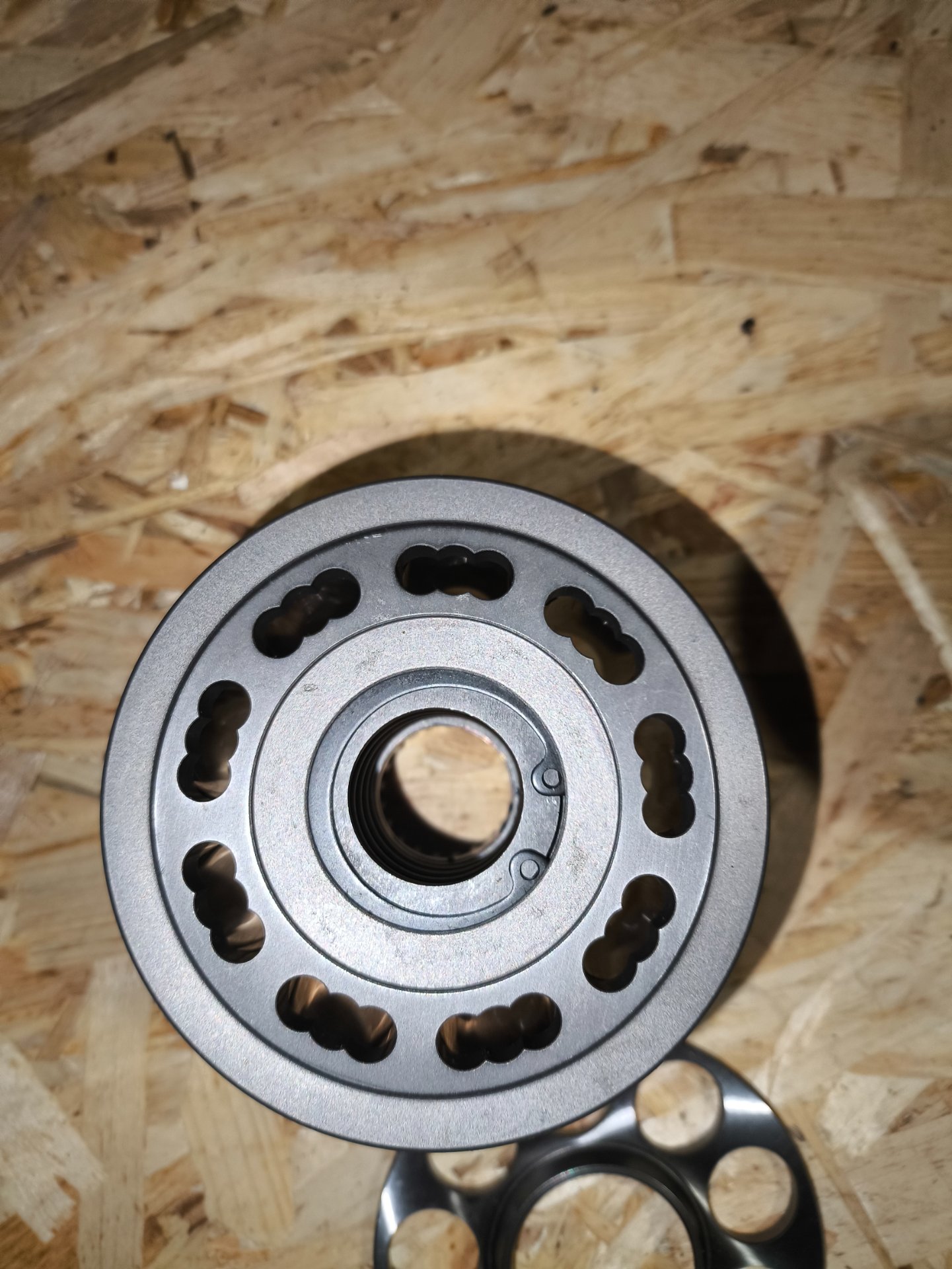
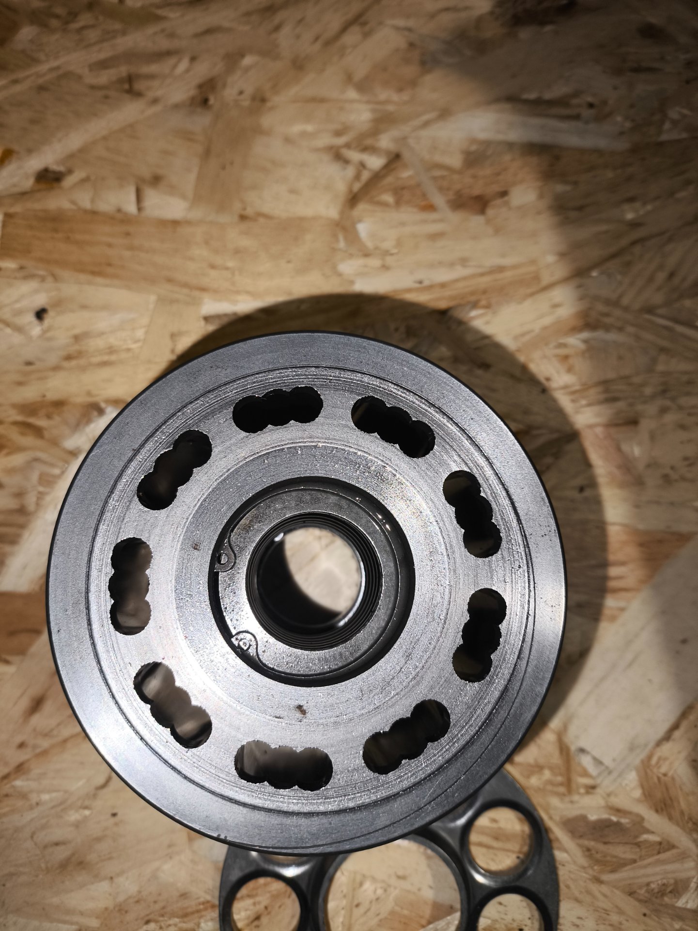
The rear cover has now been resurfaced. It ended up not being hand-lapped, but rather machined, with approximately 0.0067 inch (0.17 mm) removed.
I realize that removing this amount of material may have an impact on the original surface hardness. That said, given the condition of the part, I’ve decided to accept this risk and see how it performs.
The machinist noted that about 0.0067 inch (0.17 mm) had to be removed because the surface was wavy rather than flat, with uneven high and low areas.


I still plan to hand lap the piston block to the rear cover during final assembly to ensure proper contact. At the moment, this is how the rear cover looks — photos attached.


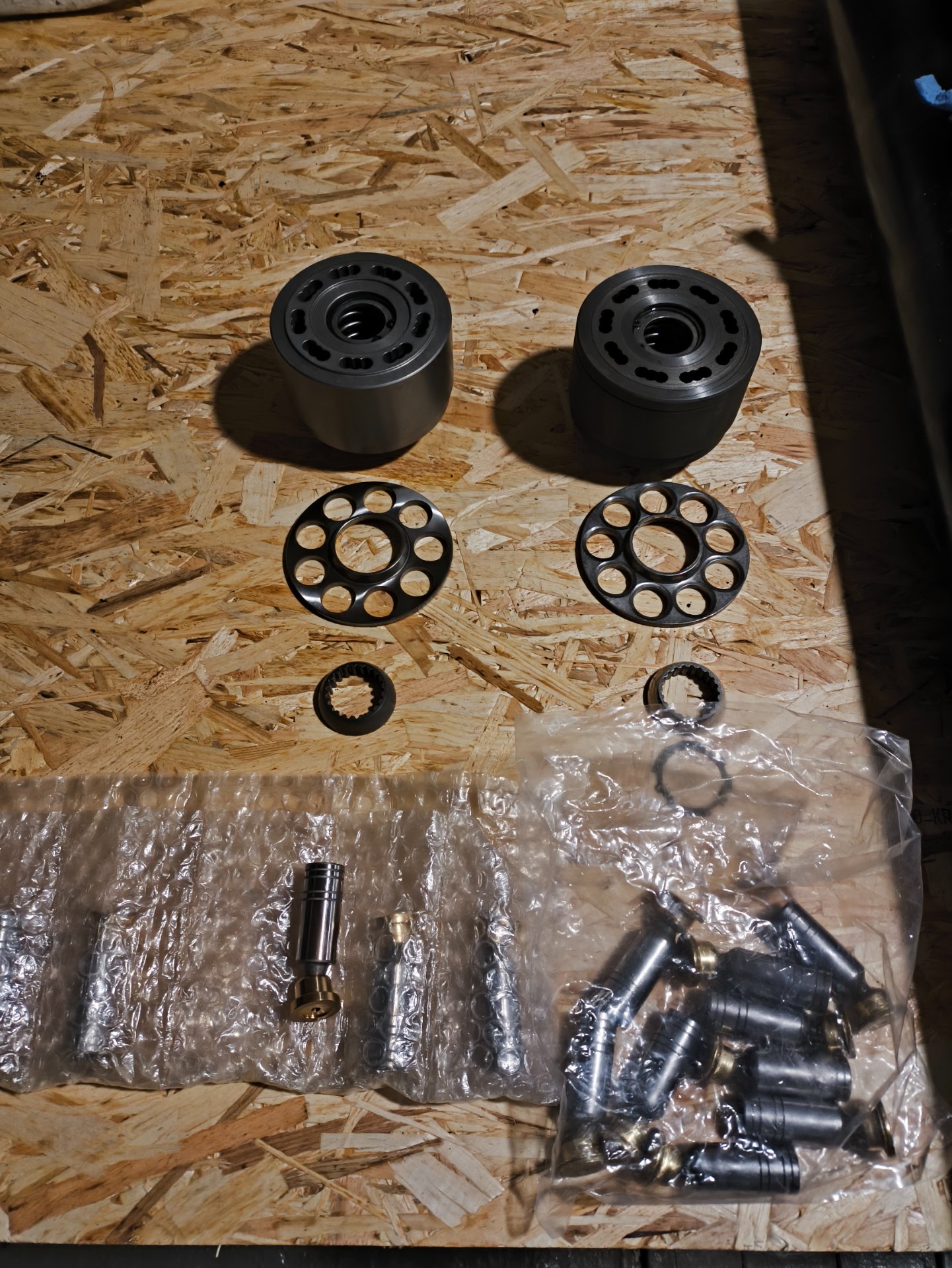
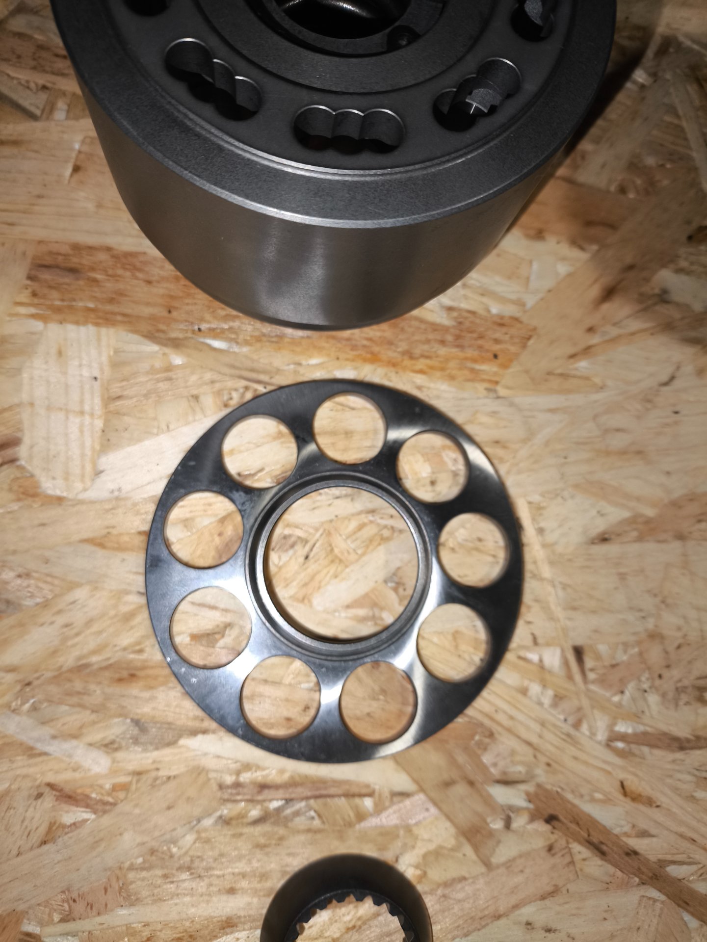
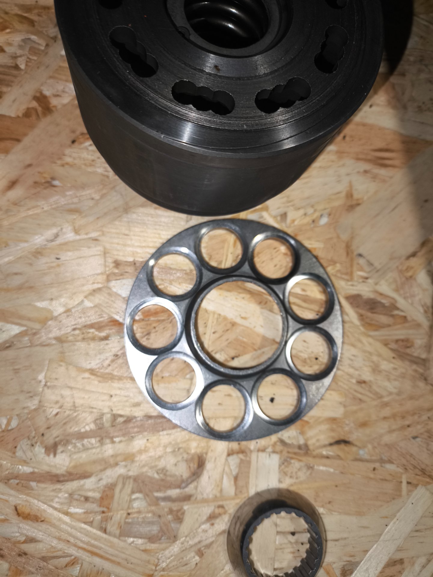
Parts have also arrived: piston block, pistons, and related components. These are aftermarket replacement parts sourced from an overseas supplier.
Before ordering, I spent several days communicating directly with the seller, asking detailed questions about dimensions, material, surface finish, and hardness. Based on those discussions, I decided to give them a try. I understand they are not OEM parts, but at this stage this seemed like a reasonable option for further evaluation and testing.


I’ll continue posting photos and updates as things move forward.
 

Attachments

  • IMG_20260118_152905.jpg
    IMG_20260118_152905.jpg
    558.8 KB
  • IMG_20260118_152937.jpg
    IMG_20260118_152937.jpg
    361.2 KB
  • IMG_20260118_152942.jpg
    IMG_20260118_152942.jpg
    445 KB
  • IMG_20260118_152946.jpg
    IMG_20260118_152946.jpg
    308.8 KB
  • IMG_20260118_152949.jpg
    IMG_20260118_152949.jpg
    305.7 KB
  • IMG_20260118_152953.jpg
    IMG_20260118_152953.jpg
    472.1 KB
  • IMG_20260118_152958.jpg
    IMG_20260118_152958.jpg
    372.8 KB
  • IMG_20260118_153010.jpg
    IMG_20260118_153010.jpg
    461.8 KB
  • IMG_20260118_153026.jpg
    IMG_20260118_153026.jpg
    293.4 KB
  • IMG_20260118_153031.jpg
    IMG_20260118_153031.jpg
    331.5 KB

Latest posts

Back
Top