853 valve identification please

Skidsteer Forum - Bobcat, New Holland, Case, John Deere

Help Support Skidsteer:

mike11

Well-known member
Joined
Nov 26, 2025
Messages
96
Guy hopefully you can help me out here and please be patient with my lack of familiarity with this unit at the moment. I’m no expert on this machine yet. Here’s the story on it I recently picked this machine up, seller said it needs wiring work, ok. Well it does alright! Someone removed ALL boss and aux wiring and controllers, installed a non boss harness with analog gauges, which will run the machine but I want the aux hyd to work like they’re supposed to. So I purchased the correct controller for the machine, I’m going to most likely have to build a harness for it, now while looking at the schematics, there are 2 variations of the wiring,
1 with front aux valve control harness and
1 without
Which would be correct ? I also need to ID 2 valves, each is along the main frame behind the controls up under there.

The schematic says I must wire to front aux rod sol and front aux base sol, could someone please point me to where they are.

It looks like there was a horrible Frankenstein job to make the aux work in the past but it looks like it was never finished and that person can not be contacted so I’m starting from scratch.

As far as gauges go I’m putting a few in with senders which will be fine. I do how ever need to get a plug onto the sender plug for the fuel tank, is that accessible without removing the engine ???

Thanks for all your help and insight
 
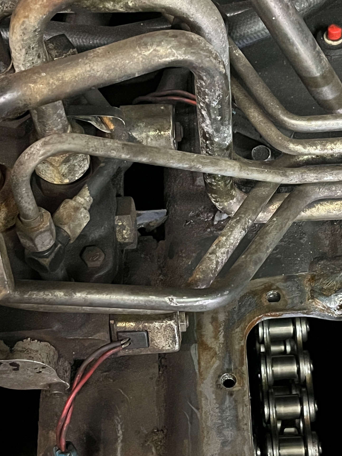
I am just finishing my 853 with the Boss system and I found the 2 connectors with 2 conductors each if you are operating that will be on the left side under the seal rest plate.
I did connect the fuel gage connector with the power plant installed.
I have the 4jb1 engine.
 
I am just finishing my 853 with the Boss system and I found the 2 connectors with 2 conductors each if you are operating that will be on the left side under the seal rest plate.
I did connect the fuel gage connector with the power plant installed.
I have the

I am just finishing my 853 with the Boss system and I found the 2 connectors with 2 conductors each if you are operating that will be on the left side under the seal rest plate.
I did connect the fuel gage connector with the power plant installed.
I have the 4jb1 engine.
I got a new aux controller, now I need to build a harness for it, what I need is to identify the solenoids and locations so I can properly wire them up
 
The schematic says I must wire to front aux rod sol and front aux base sol, could someone please point me to where they are.
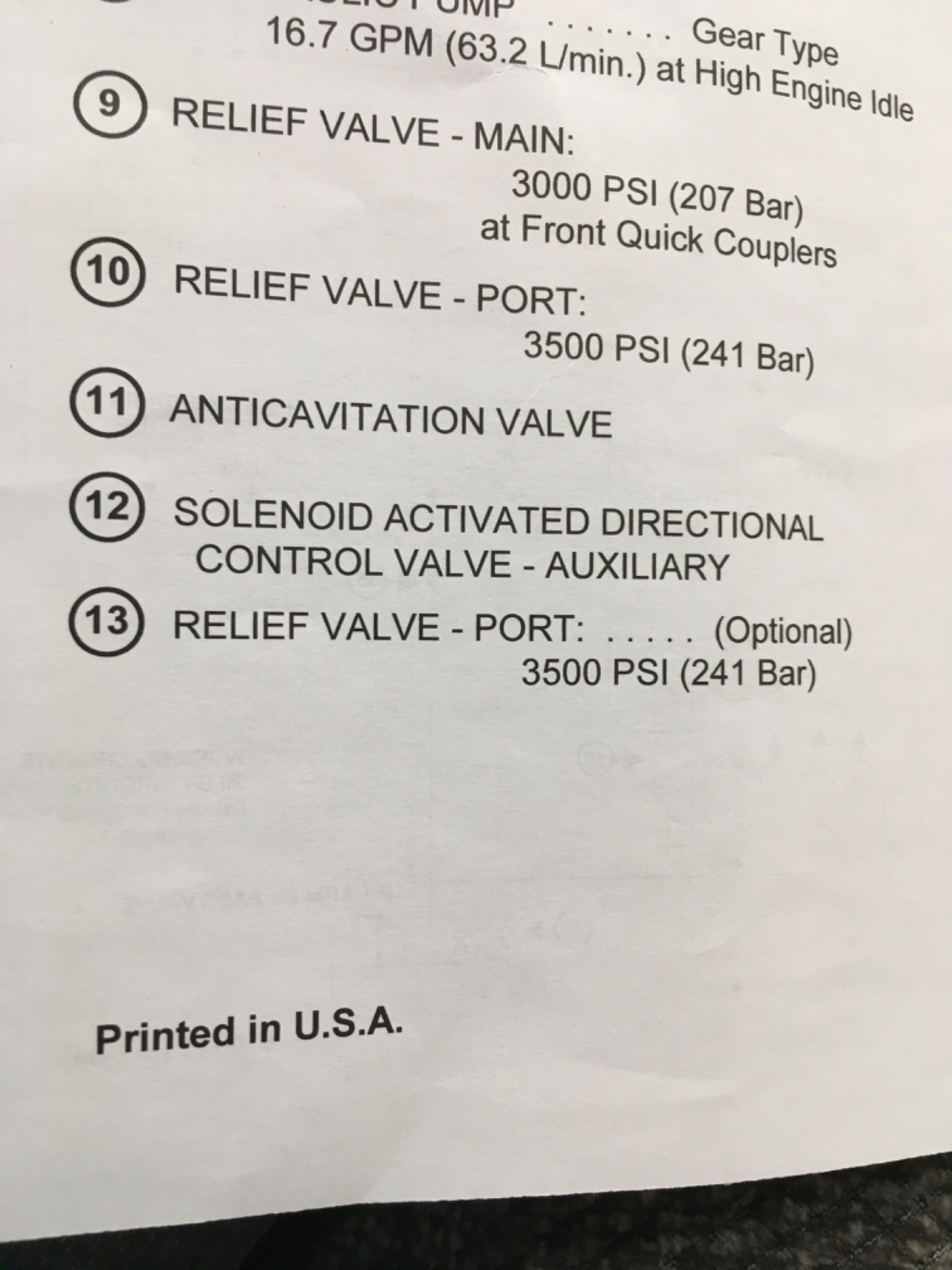
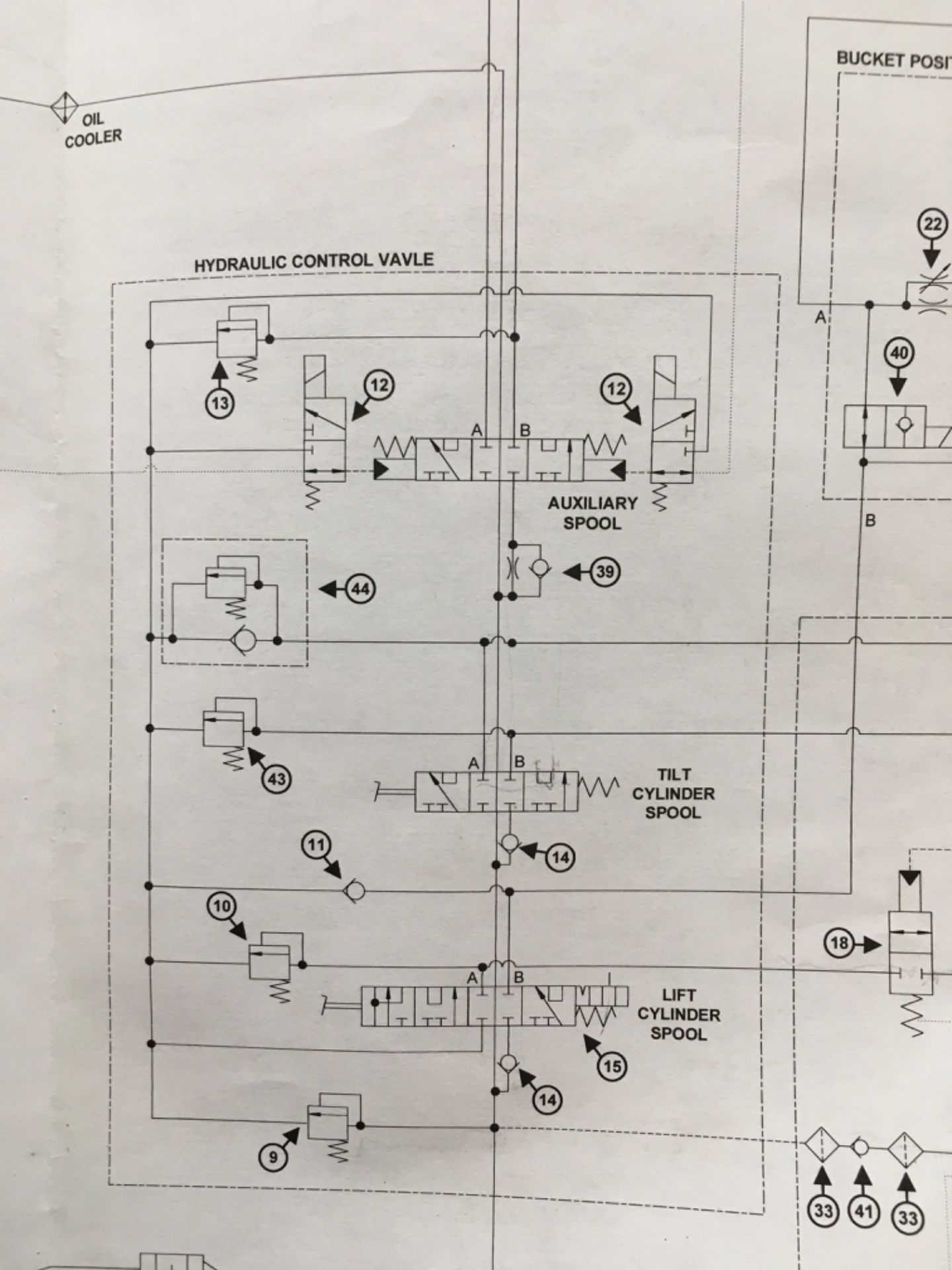
I’m not sure on the 853, not familiar with it. But, on my 773 the auxiliary solenoids are on top of the main control valve. Item number 12.
Hope this helps
 

Attachments

  • image.jpg
    image.jpg
    496.2 KB
  • image.jpg
    image.jpg
    434 KB
Yep same on this one they’re on the control valve, can anyone answer if rod and base are male or female on the aux
Thanks
 
As an Amazon Associate we earn from qualifying purchases. Product prices and availability are accurate as of the date/time indicated and are subject to change.
On my non-BOSS 853, the Aux Controller harness goes from the main wiring harness to the Aux Controller (that’s a blinding glimpse of the obvious, I realize). From the Aux Controller, the wires continue on to my Apitech auxiliary valve. What I learned with my non-BOSS machine is that the Aux Controller does not use the PWM – pulse width modulation – switches. The Aux Controller has simple on/off (or open/closed if you prefer) micro relays encased in an epoxy housing. There may well be diodes and other electronics in the controller, but the simple output is on/off.

I seem to recall that there was more than one model of Aux Valve, which is to say that not all 853’s had an Apitech valve. You can see what an Apitech valve looks like by clicking here. That is only one complicating factor. With your BOSS non-BOSS machine, you have to figure out how it worked originally, as a BOSS machine, and then figure out what has been added/removed, in order to get it running. As in, did the BOSS version have the Aux Controller already built in to the electronics? Does the 853 BOSS serial number use PWM switches on the handles? How were the Aux Valves plumbed in your serial number? These are all rhetorical questions because the universe of people that have your same electrical situation is probably a universe of 1.

Setting all that aside, follow your hydraulic tubing from the control valve power beyond port and see where it goes. Test the switches in your drive handle to see if they work. They could be PWM switches, but consider that they could be just open/closed switches that are broken. Mine were. PWM non-PWM switch discussion here. If whatever Aux Valve you have connected to your power beyond port has 12 volt, non-PWM solenoids, more details here, then get 2 Bosch 12v relays and test it to make sure it works and allows flow in two directions. Test whatever controller you bought as well.

If everything works, then you’re off to the races.
 
Wateka Thank you !!!

according to bobcats website my serial no uses the non pwm controller which i was lucky enough to get a new NOS unit, what is a lil foggy is the drawings for the control harness, the schematic shows 2 variations, one with front aux valve control harness and one without, in my situation i have no harnesses and no idea what it had, but i will build or gets what is needed, just not sure which of those 2 options i should or need to go with, I am leaning toward the drawing with no front aux control harness that shows that hi pres can be bled off with the acc position of the key as it is described in the manual. Which leads me to the last few foggy areas and I think it will come together and work well On the apitech valve, which connection is for hi flow and which is for hi pres.? Also where would the aux pres relief sol be located in the machine. with that info I should be able to wire it all up and be good to go. I was able to get my hands on an aux controller harness NOS pt no 6705283 but as I mentioned I believe I will need the 6702999, but that is not a big issue, I will mod the 5283 to be a 2999 theres only a few added circuits. The hi flow harness is pretty cut and dry I will build one of them, thats not a prob, I have everything here to do that. I have diodes here and all needed plugs and connectors ect.
 
On the apitech valve, which connection is for hi flow and which is for hi pres.?
My unit is a standard 853, not an 853H. That said, my understanding is that when you activate the High Flow pump, that’s what you get. High flow. (Plus a bump in system pressure from 2300 psi to 3300 psi). If the high flow supply goes to the control valve, then the plumbing does not change. An operator controlled electrical switch somewhere just toggles the high flow pump on and off. If it goes to the Aux valve, then you’ll have to see who made the valve. In looking at my old Apitech pictures, there were no unused ports where you could add the high flow pump connection.
 
Last edited:
Yep same on this one they’re on the control valve, can anyone answer if rod and base are male or female on the aux
Thanks
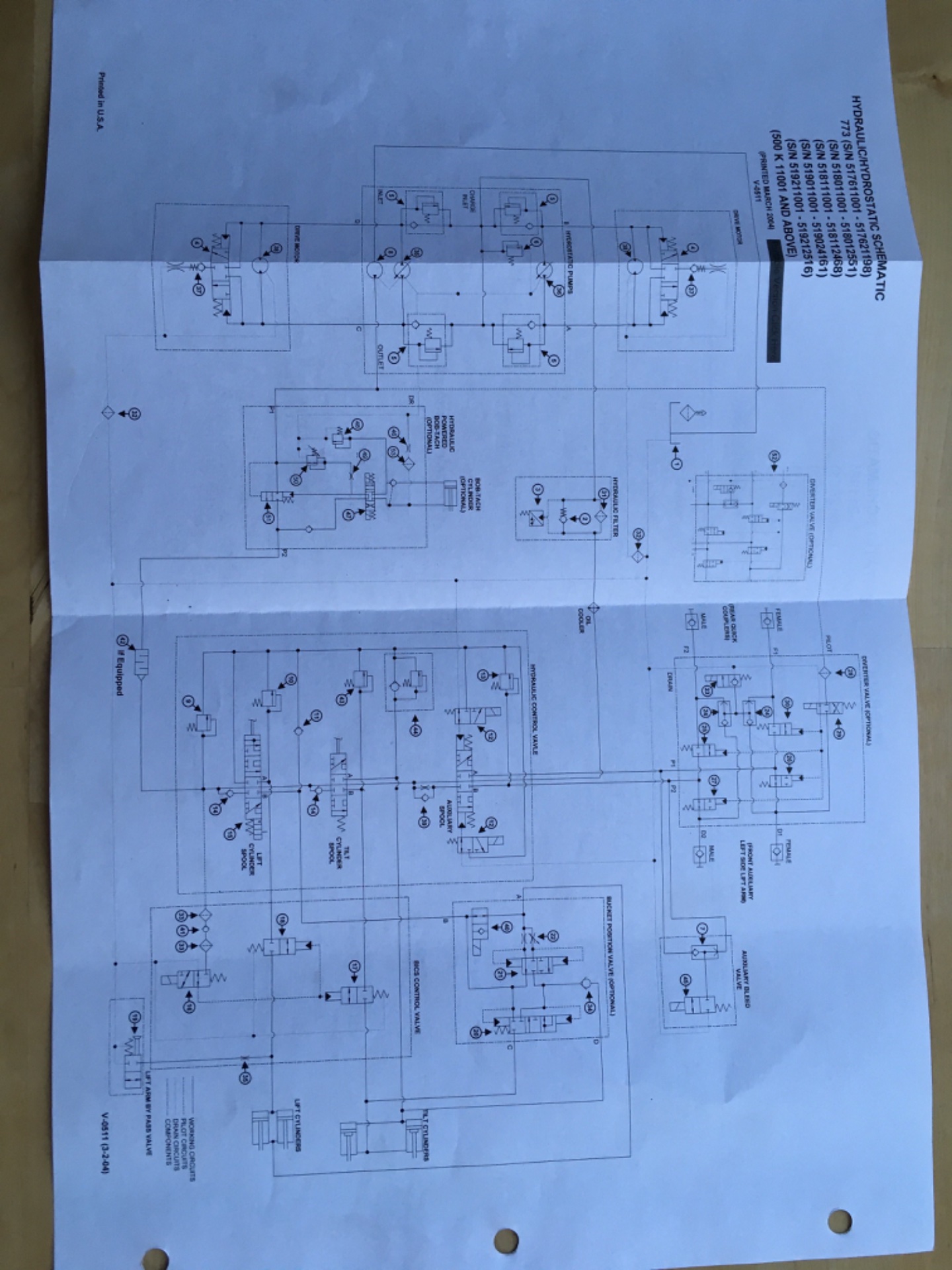
Rod and Base usually refers to the rod end of a cylinder or the piston end of a cylinder. Not sure how that applies to the male or female aux couplers. Here is the schematic for my machine 773G, no idea if yours is the same or if this answers your question or not. When the front solenoid is activated it moves the spool and sends hyd pressure to the Female (top) aux coupler. When the rear solenoid is activated it moves the spool and sends hyd pressure to the male (bottom) aux coupler.
 

Attachments

  • IMG_1560.jpeg
    IMG_1560.jpeg
    489.3 KB
My unit is a standard 853, not an 853H. That said, my understanding is that when you activate the High Flow pump, that’s what you get. High flow. (Plus a bump in system pressure from 2300 psi to 3300 psi). If the high flow supply goes to the control valve, then the plumbing does not change. An operator controlled electrical switch somewhere just toggles the high flow pump on and off. If it goes to the Aux valve, then you’ll have to see who made the valve. In looking at my old Apitech pictures, there were no unused ports where you could add the high flow pump connection.
The apitech in this one has a handful of electrical connectors on it, May be for pwm control. I need to know which one opens flow in that valve. From the schematic it’s pretty simple on the hi flow side. I think I’m pretty close to having this all figured out
 
Rod and Base usually refers to the rod end of a cylinder or the piston end of a cylinder. Not sure how that applies to the male or female aux couplers. Here is the schematic for my machine 773G, no idea if yours is the same or if this answers your question or not. When the front solenoid is activated it moves the spool and sends hyd pressure to the Female (top) aux coupler. When the rear solenoid is activated it moves the spool and sends hyd pressure to the male (bottom) aux coupler.
Thank you that’s what I needed, the main control valves other than safety stuff didn’t change much. And I’m sure the config m/f out front is standard
 
Mine is located basically right underneath the seat under the cab on top of the chain case. You’ll see a small solenoid valve with 2 small hyd hoses (#4 hoses I believe) running to each of the main aux hard lines. There is a 3rd small line that drains back to the tank or a case drain line. It’s -38 degrees and I pulled my machine outside and parked it, otherwise I would go get you a photo.
 
Mine is located basically right underneath the seat under the cab on top of the chain case. You’ll see a small solenoid valve with 2 small hyd hoses (#4 hoses I believe) running to each of the main aux hard lines. There is a 3rd small line that drains back to the tank or a case drain line. It’s -38 degrees and I pulled my machine outside and parked it, otherwise I would go get you a photo.
Thank you, I’ll find it with that info. Also looking for the diverter sol, with that I can finish this up and think I’ll be good, I have a harness made ready to go it, just waiting on the aux switch to get here
 
Thank you, I’ll find it with that info. Also looking for the diverter sol, with that I can finish this up and think I’ll be good, I have a harness made ready to go it, just waiting on the aux switch to get here
I don’t have a diverter valve on mine, but my service manual shows it right behind the main control valve on the right side of the machine. It is a silver colored valve block.
 
I don’t have a diverter valve on mine, but my service manual shows it right behind the main control valve on the right side of the machine. It is a silver colored valve block.
I’ll have to look n see I do have a valve on the outside wall on the right side behind the main control valve that may be it
 
Dug into this machine a lil, actually a lot deeper this weekend. I’m trying to figure the wiring out in here as I bought a harness which isn’t 100% accurate but that’s not a issue, with the schematics I’ll make it work how it needs to.
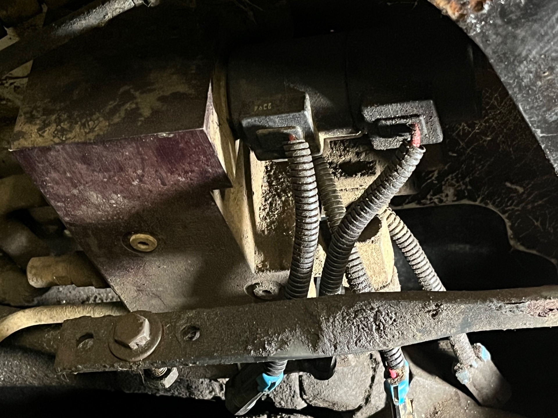
There’s only a handful of solenoids in the machine. One on the right side wall wired up to a switch this one locks the machines hydraulics down. I’m assuming this is the press to operate circuit. That I’ll leave alone.
Other than that I have 2 on the main control valve, for aux hydraulics. And (4) on the apitech valve. 2 on 1 spool and 2 single valves. Correct me if I’m wrong, 1 being for hi flow on/off and the other for hi pressure ?? The single spool with 2 solenoids for variable flow ??? I need to identify what’s what so I can wire this up properly. Any help is much appreciated. Pics of the valves attached

Thanks
 

Attachments

  • IMG_8428.jpeg
    IMG_8428.jpeg
    760.4 KB
  • IMG_8427.jpeg
    IMG_8427.jpeg
    733.9 KB

Latest posts

Back
Top