Glad to hear she lives again peebeeaitch. Skid steers are the only thing I've seen that keep getting brought back to life. Makes me wonder where the used parts come from because I never see them parted out. There was a M444 redone on craigslist this past winter.
15 July 2013
After a break in work for the last couple of weeks because I was away, I decided to tackle the little machine again.
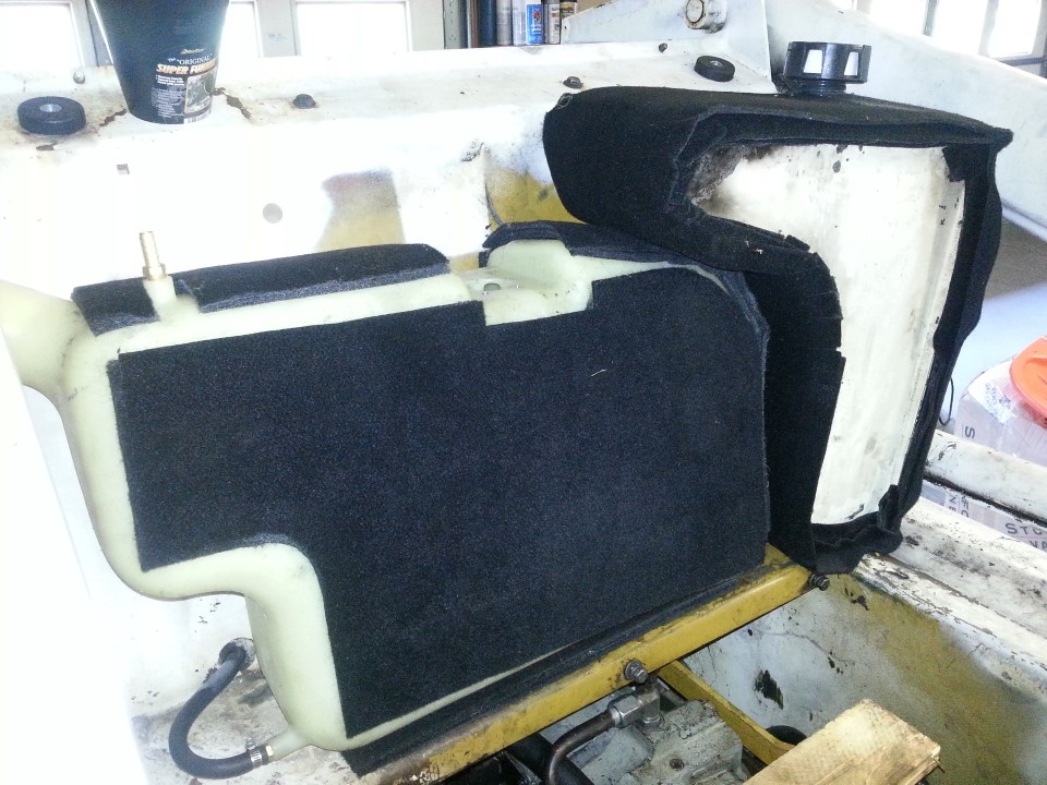
I think I have tried to find the foam for padding the fuel and oil tanks everywhere. Obviously they're not made anymore (which I was hoping against hope), and trying to find something online or at Menards proved pointless. I was doing the isle-by-isle thing at Wal-Mart and found some aftermarket auto floor fabric. Having used some sprayable contact adhesive before, this is what I came up with:
This is triple layer...
I also, inadvertently, sprayed some of the contact adhesive on the outer layer of the fabric. This is a great thing to do as when one locates the tanks in the correct position, the large adhesive area holds the tanks in place just enough to prevent them flopping around.
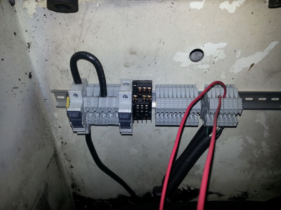
Now that the tanks were semi-located, I got cracking on the beginnings of the new wiring:
What I have found depressing about this whole reclamation story is how moving to a new country has destroyed the stock of parts and tools I used to have to my disposal. For example, I had a drawer full of fuses - all shapes and sizes and amperages. I cannot find this drawer anywhere in the hundreds of boxes of lying around in storage. The result being that I needed to stop the wiring while I jumped online to order some new (and as soon as I can find the drawer) duplicate fuses. The same with the bridging bars on the terminals.
22 July 2013
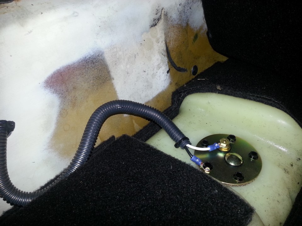
The aftermarket fuel level sender was purchased online, which installed looks like this:
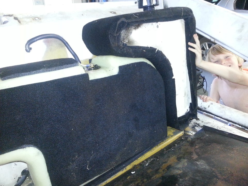
I forgot to take a photo of the fuel vent which was the last item preventing the "firewall" being reinstalled. As I fitted the firewall, I was gratified that some of the bolts could just catch the threads of the nuts when installing. My choice of 3 layers was (I feel) justified - it is a really snug fit.
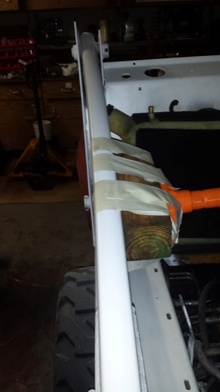
What was not a snug fit was the horizontal spacing of the oil and fuel tanks which at the point where they touched each other was in effect 6 layers of fabric. This prevented the firewall's bent steel lip from reaching around the edge of the oil tank on the one side and the edge of the tank on the other. Luckily the fabric was quite easy to remove from the one side of the fuel tank, which brought the layer thickness between the two down to 3 (I had originally thought that 6 might be too much, but I would rather have had a too tight fit rather than a clanging and bashing behind me as the fuel and oil tanks flop around. That, combined with the fuel leaking out of the vent and splashing me, turning me into a potential roman candle, was the justification). So, this is the mod (with human clamp assisting):
BTW: If you ever want a magnet that picks up dog hair, spider webs (unseen in years), blades of grass, every bit of dust in the area, or any other item that might be considered dirt, simply spray something with contact adhesive, try really, really hard to keep it clean and somehow, the now unclean item will have collected it all.
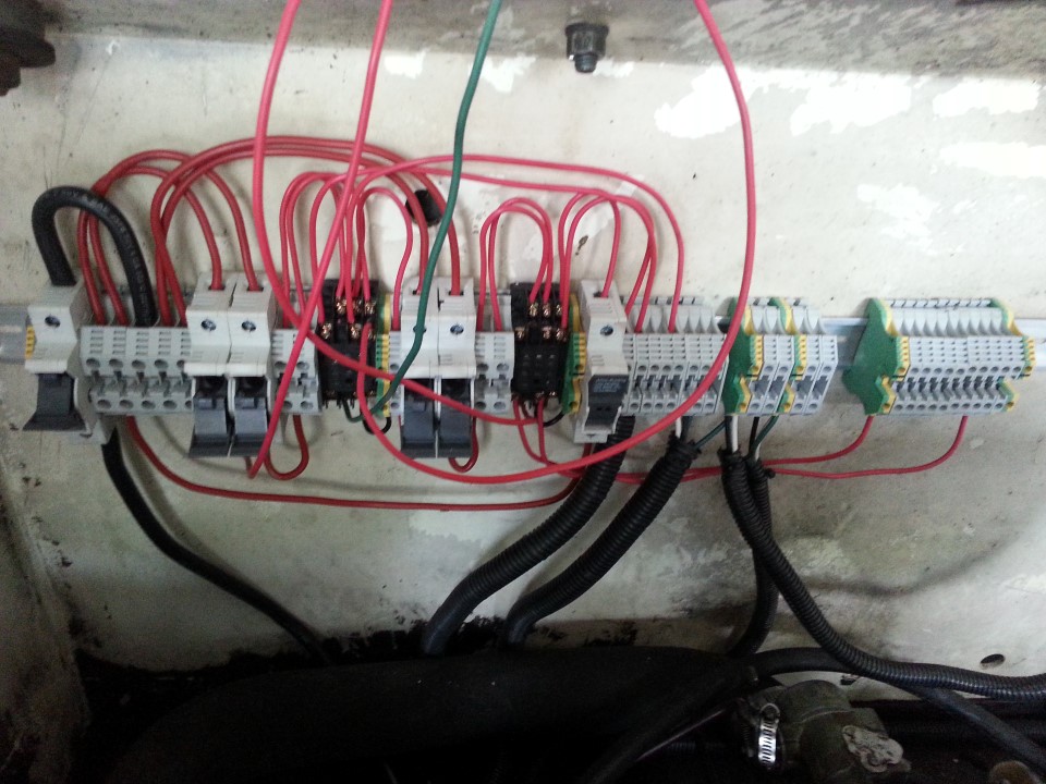
Back to the wiring:
Some progress. The wires leading off to the top of the photo are temporary supplies to the main and starter switches which will be replaced when I have an instrument panel again.
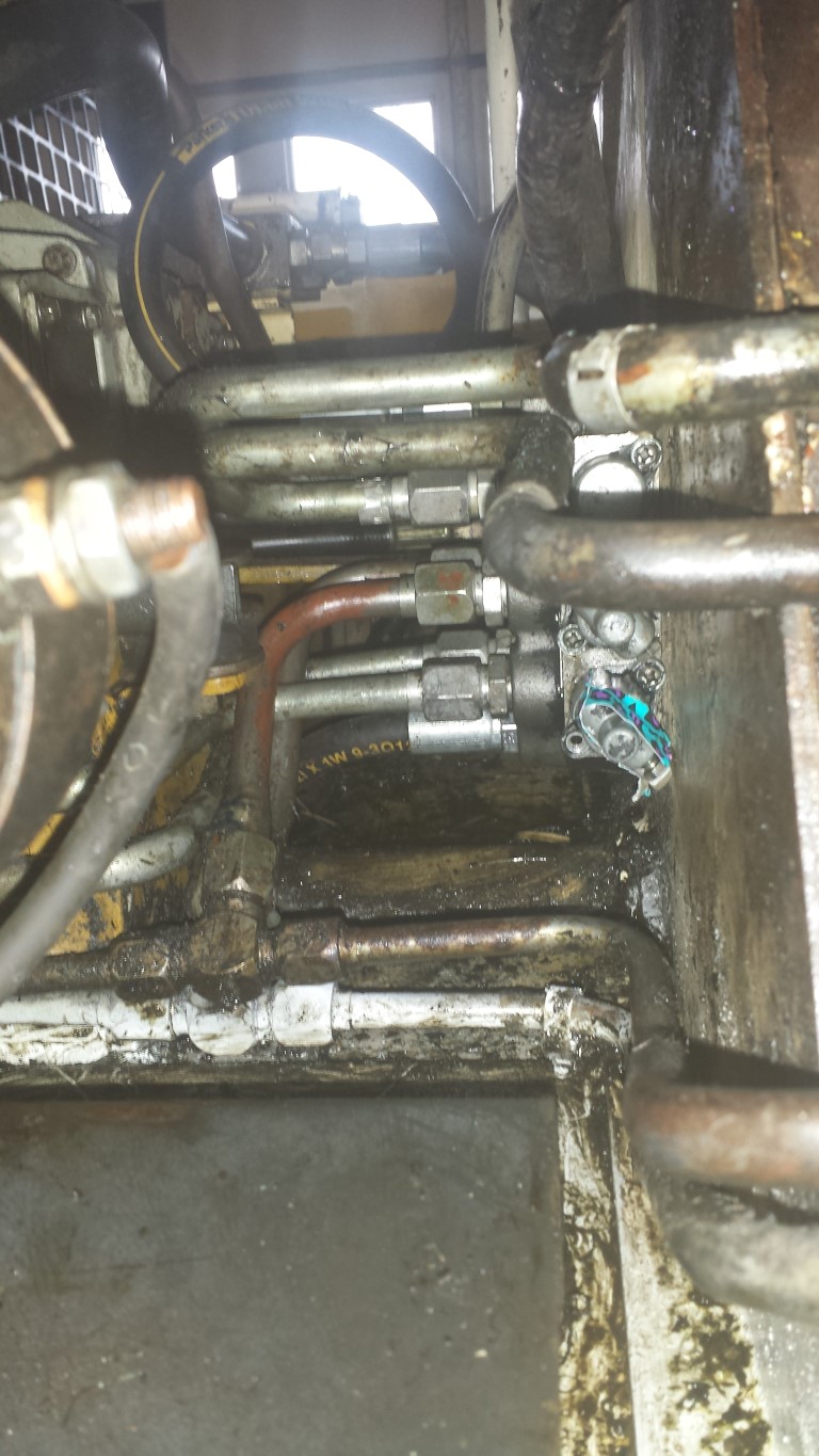
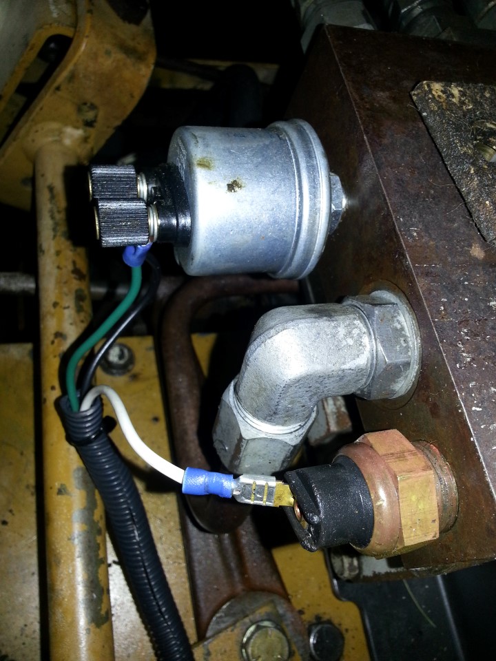
The aftermarket hydraulic pressure sender and original hydraulic temperature sender:
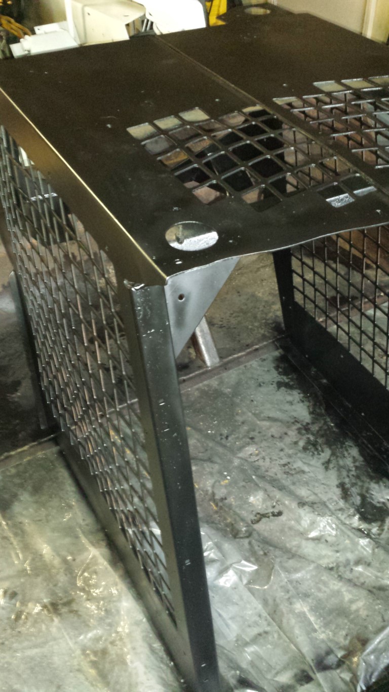
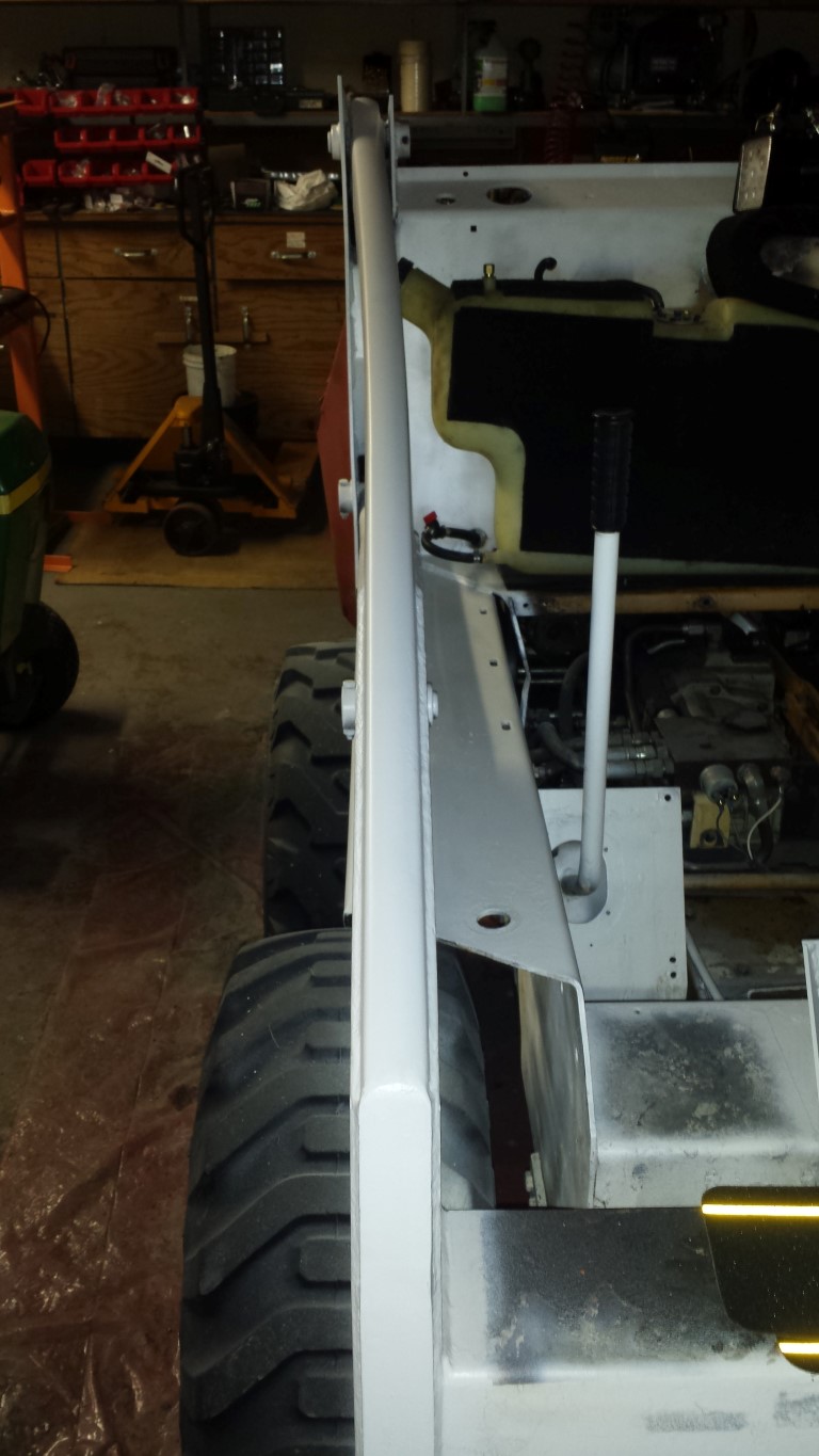
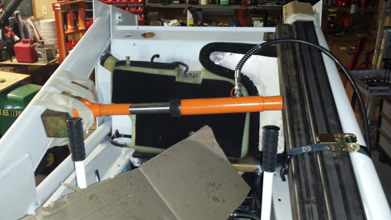
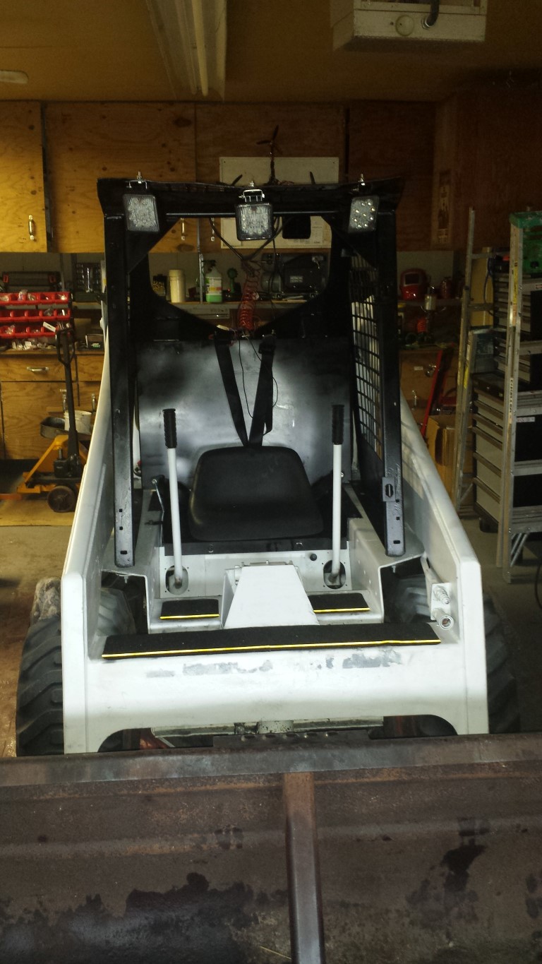
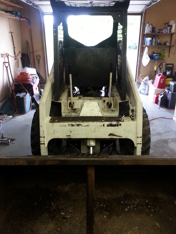
HeMan here does not have a helper, so I needed to man-handle the ROPS into place. Notice the new handles on the yank-ems:
At this point, the ROPS would not go back fully due to the fuel tank projecting mm's too far and interfering with the side of the ROPS. You know the feeling: move the ROPS back off the machine, loosen the firewall, cajole the tank in another couple of mm's, hoping it's enough, tighten all of the bolts on the firewall (because the top ones can't be easily accessed with the ROPS in place), move the ROPS back in, better, but still 2mm, repeat.
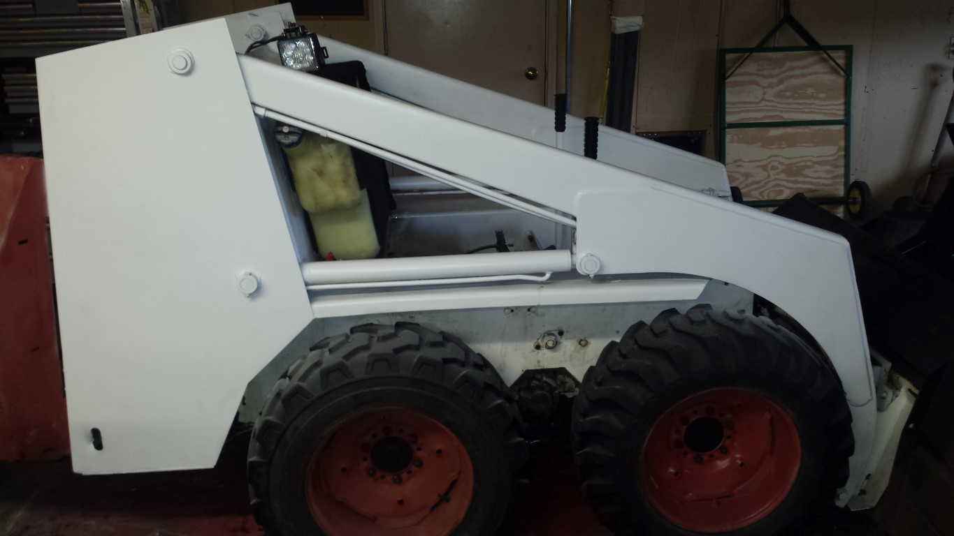
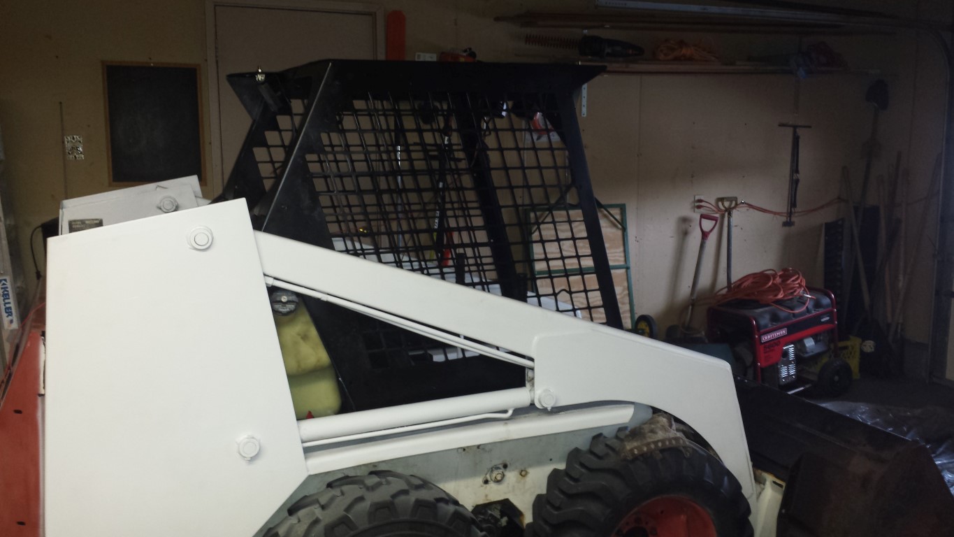
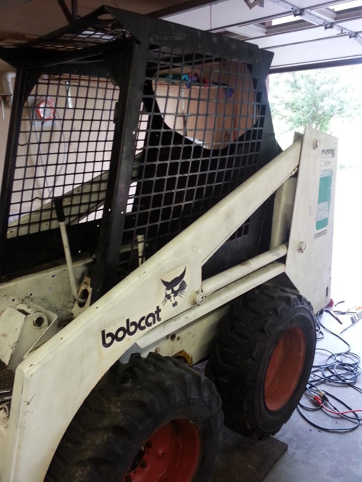
Complete:
You'll notice the little machine on jack stands. That's because the previous weekend I noticed some slop between the pintle arms and the pump. I had been through the adjustment sequence in the manual with some diligence and was sure that if I simply kept the orientation of the pusher and just took the little bit of slack up, everything should still be neutral when releasing the sticks.
Bad mistake. What I did was to adjust the right hand motor to have a slow creep forward when I released the stick. This had the effect of making the machine, in effect, a mechanical bull. The long and short of it is: there is (in my opinion) only one way to set the neutral. RTFM.
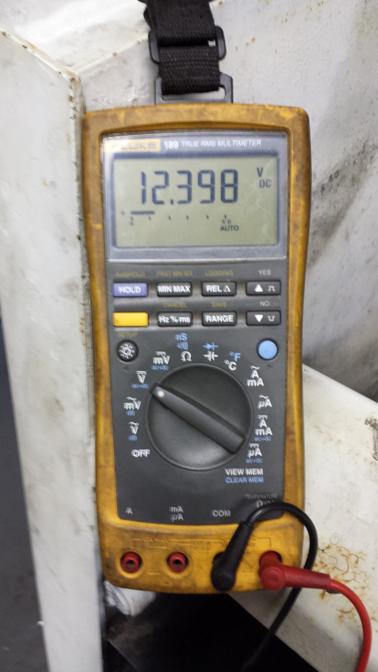
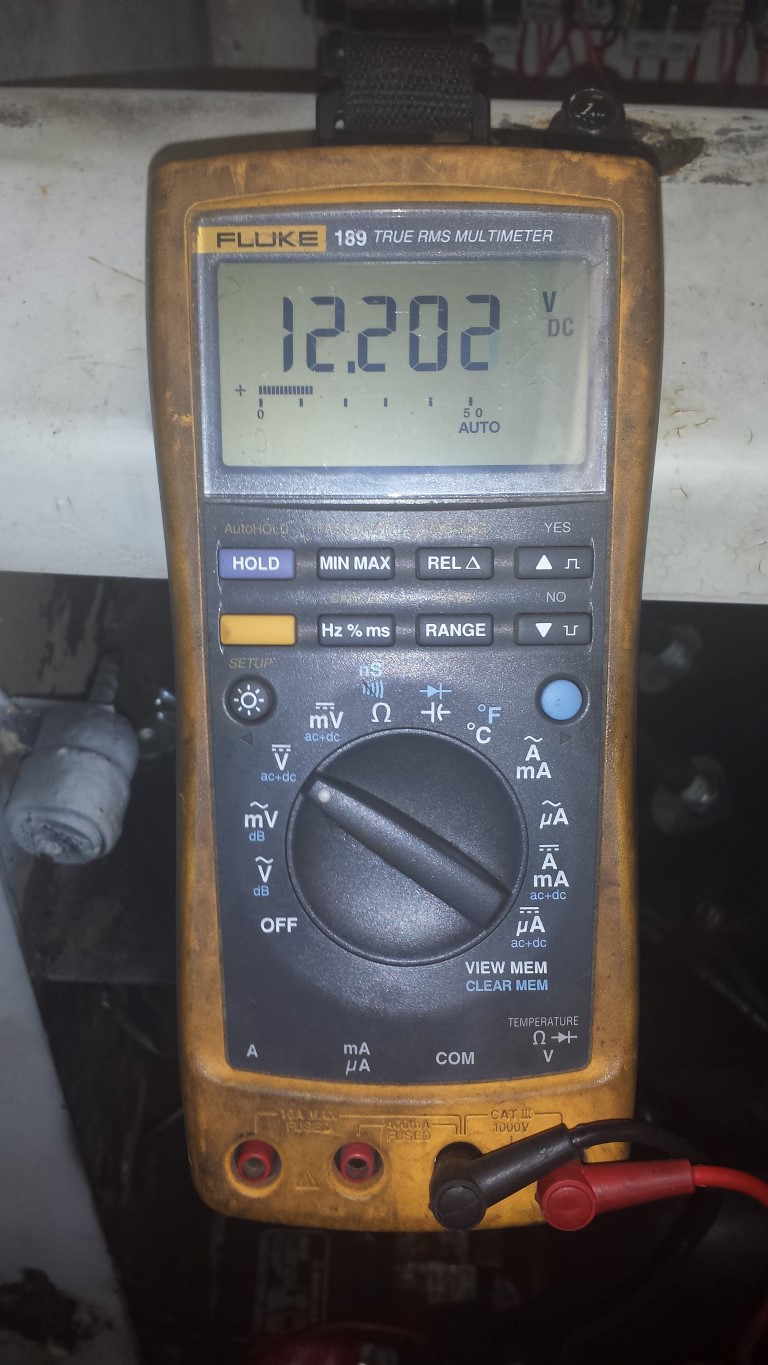
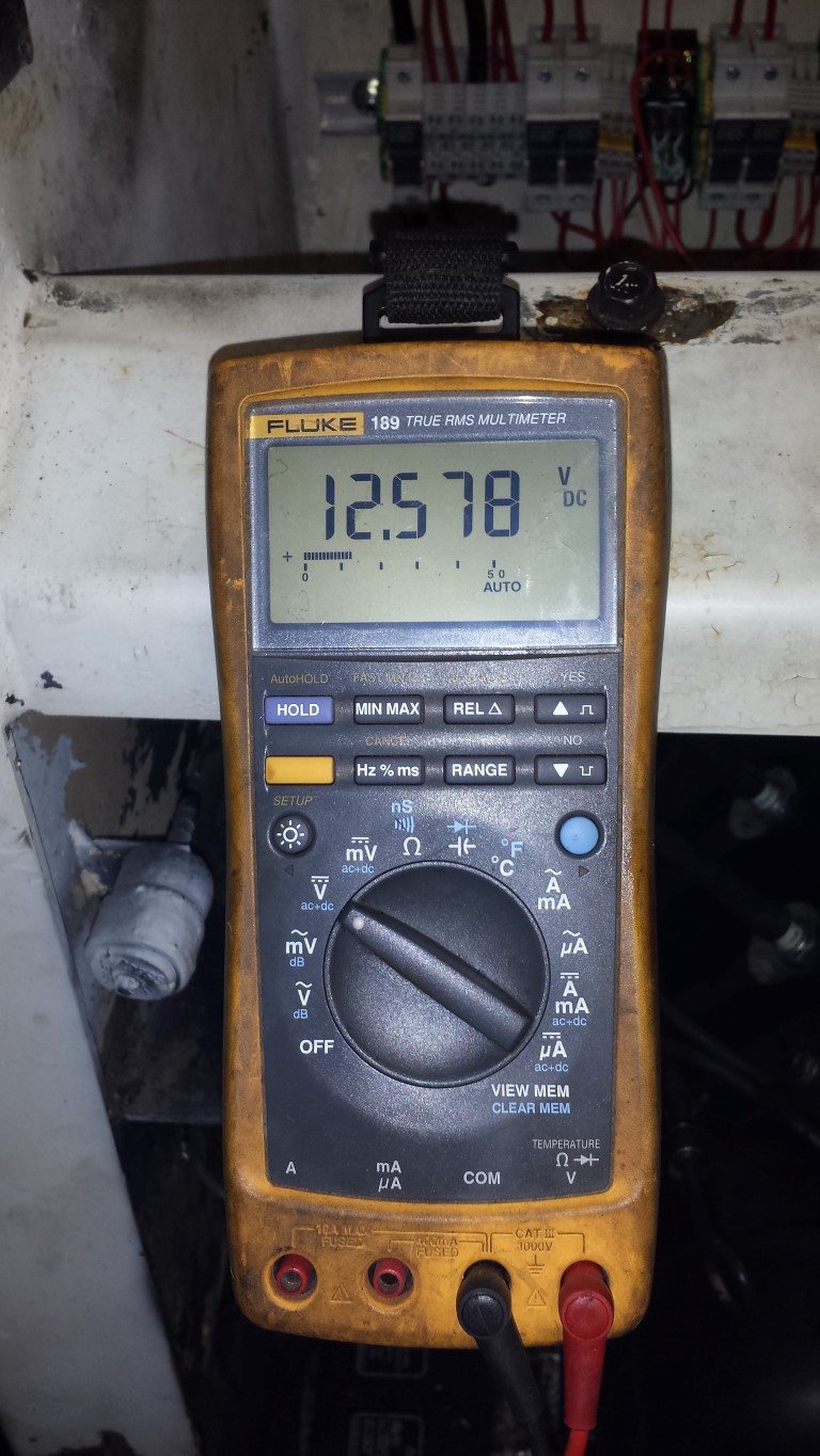
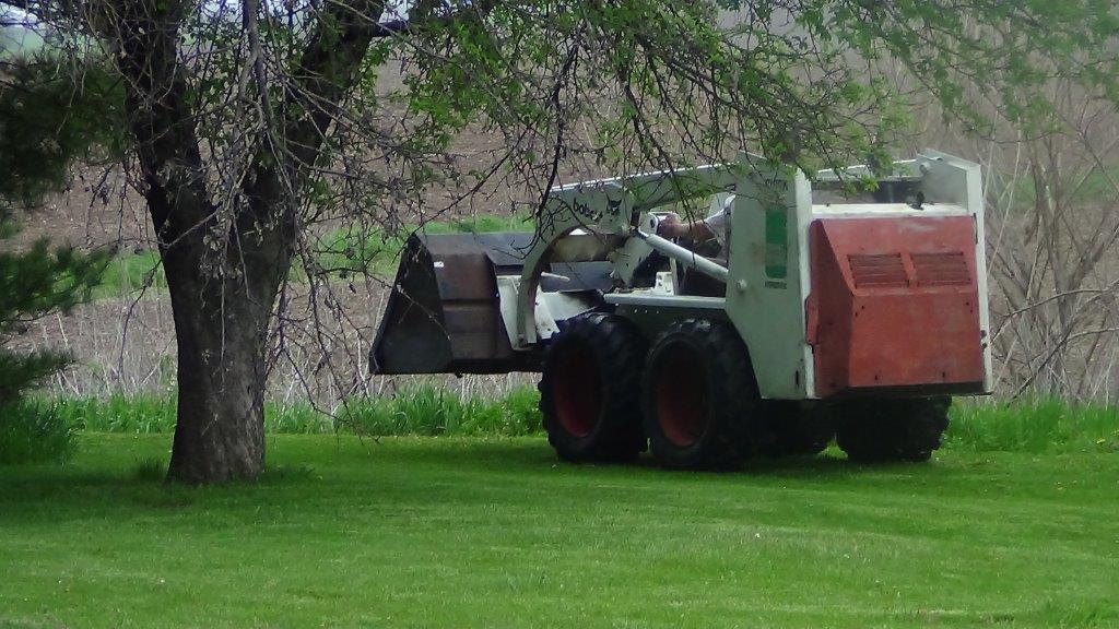
Ok, so now I have an almost working Bobcat. Except it does not charge the battery.
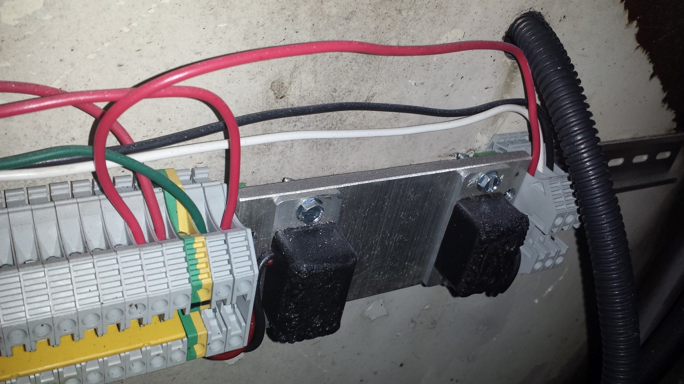
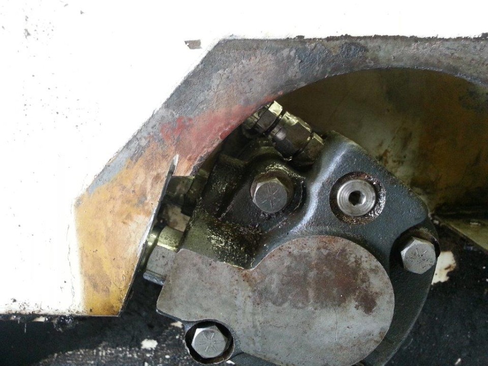
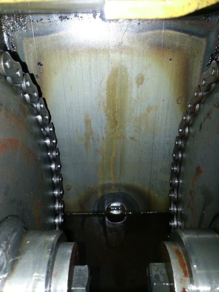
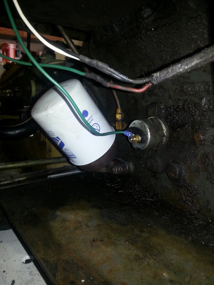
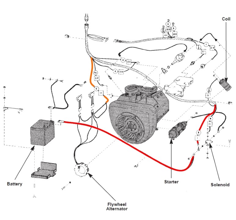
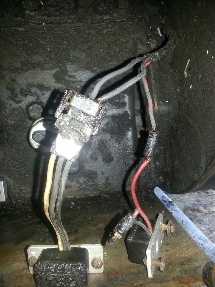
I think I have read every site on the net (literally) on how to buzz the alternator. I am still clueless. So here's what I'm going to try. In the photo below:
there are two black wires and a red to the alternator. My assumption is that the two blacks are from the armature and that the red is the field. I am going to connect the two blacks to the two blacks on the original rectifier. The third wire (white) from the rectifier I am going to assume is charge output. The red wire from the original regulator I am going to connect to the red wire from the alternator, and the other wire (black) I am going to connect to the battery.
Does anyone have anything better to suggest? Like, for example, tying the black wire from the regulator to ground?
Any help appreciated.

")