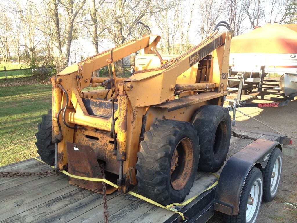
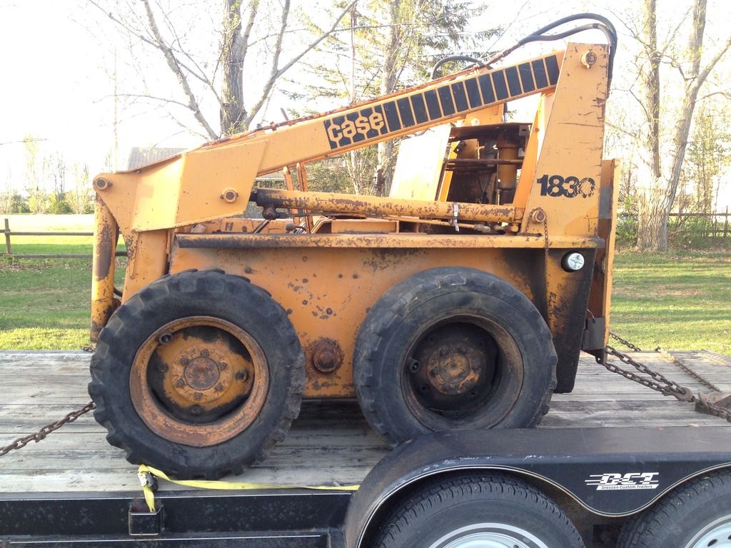
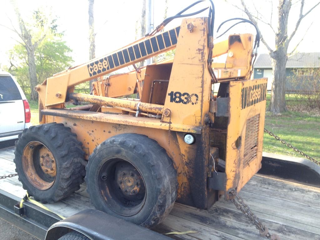
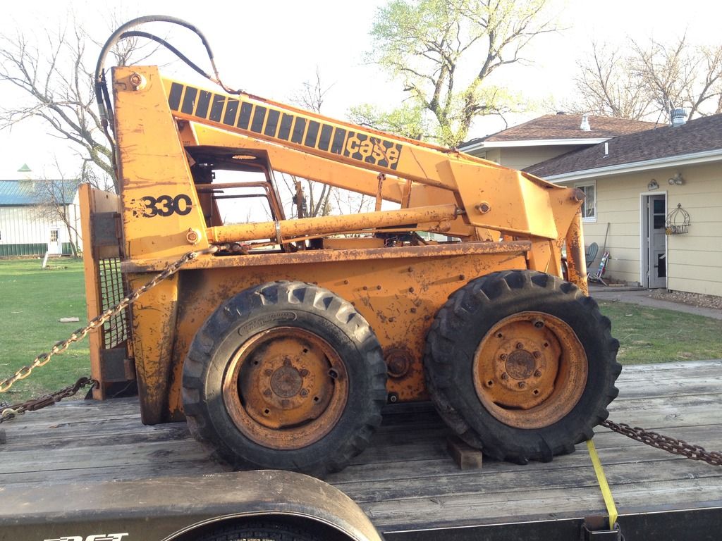
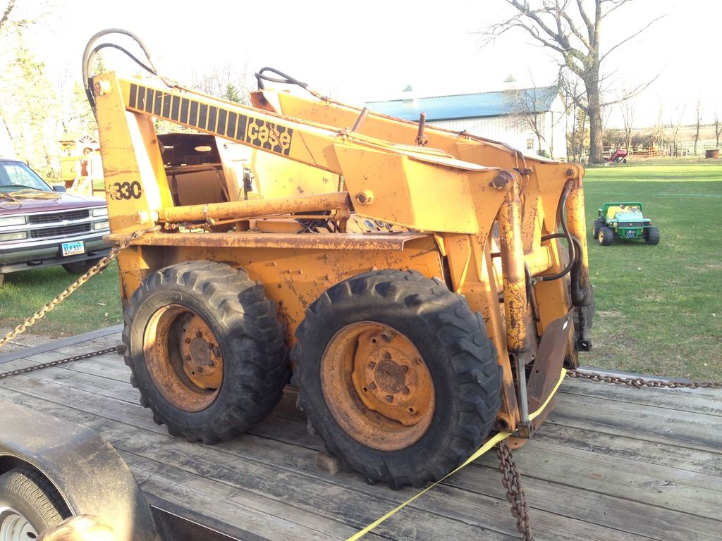
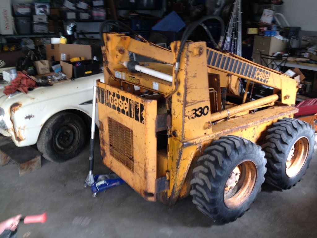
Two years ago, my Dad bought this unit from the neighbor. The unit had already been repowered once, losing the original Renault/Continental TR688 (rated at 30hp) and having it replaced by a GM 2.5L 4cyl.
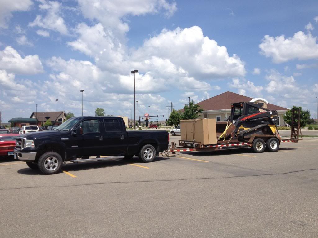
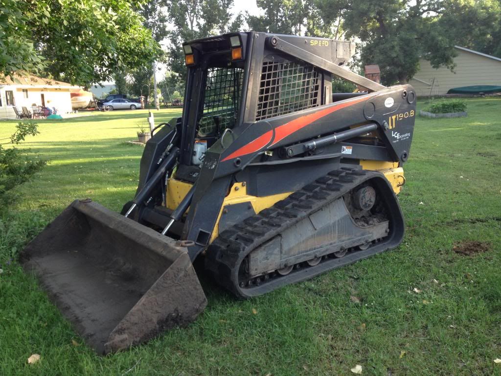
It was parked when the 2.5L started smoking and knocking, and had been parked for an unknown number of years. My Dad started tearing it down and has a couple 2.5L GM motors at his place and had planned on simply replacing the existing motor with one of the same. He started tearing into it and found that the brakes needed to be rebuilt also, so he tore those apart as well. And then in an unfortunate turn, his health prevented him from reassembling it. So after sitting at his house for almost 2 years with no motor, and the brakes apart; I loaded it up on a trailer and brought it to my house.
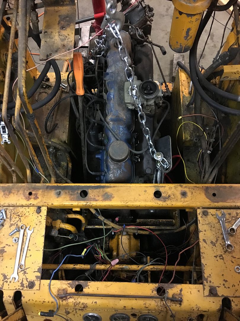
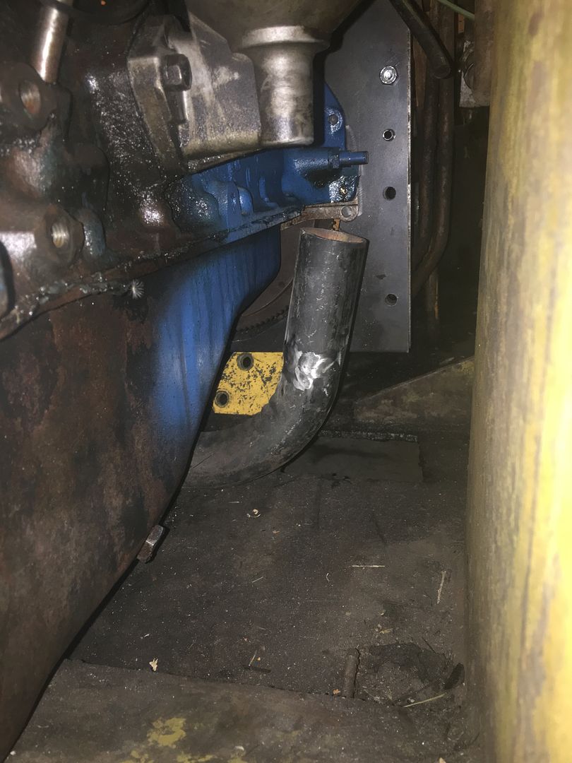
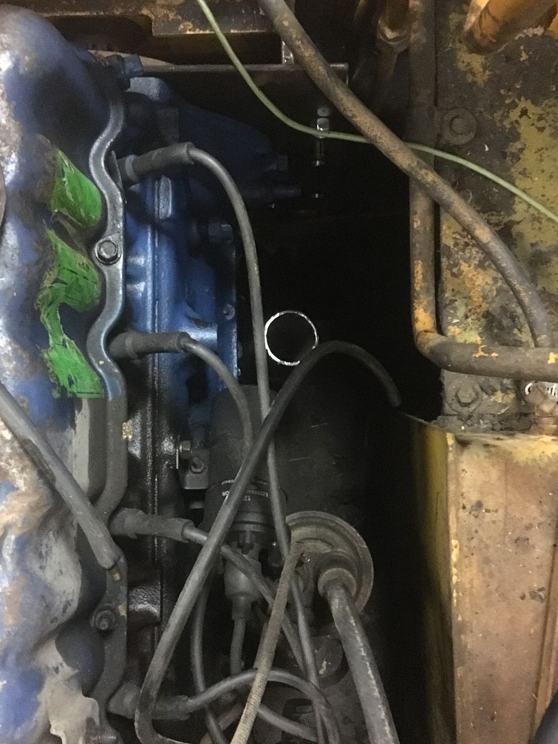
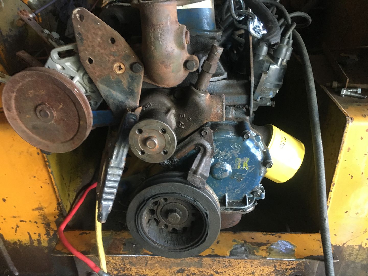
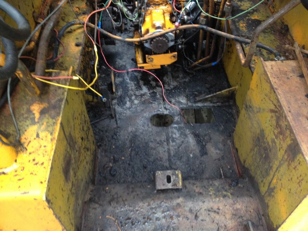
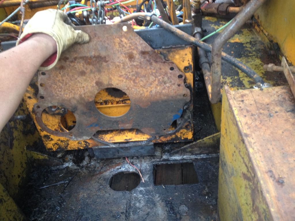
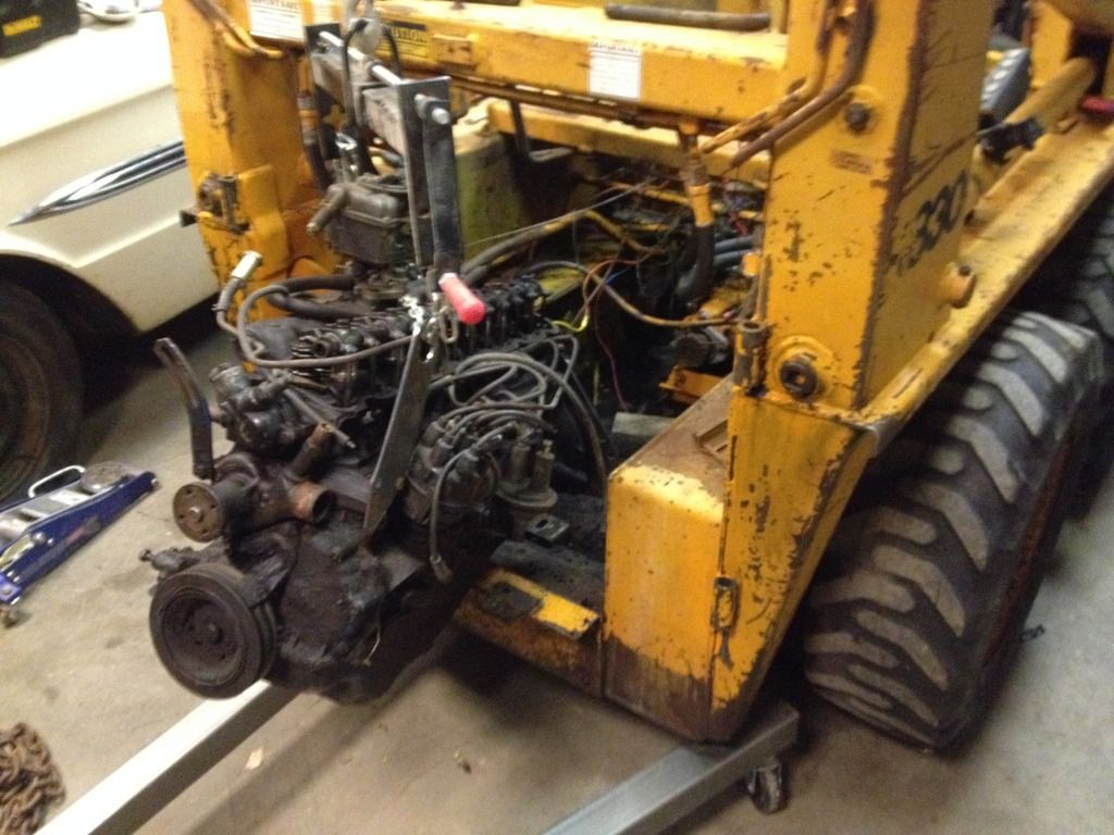
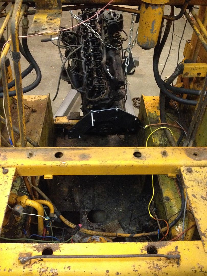
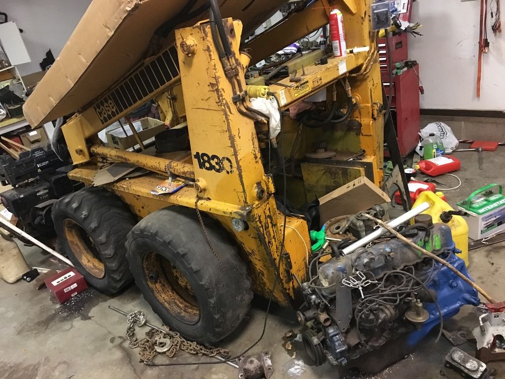
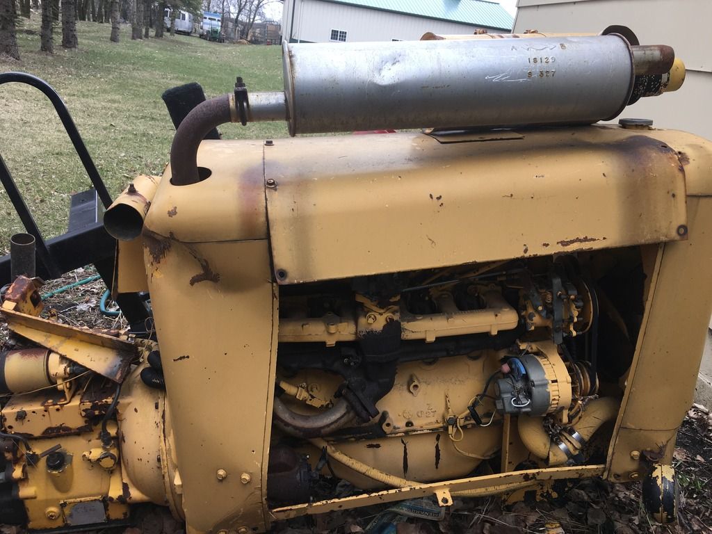
The engine bay virtually void of anything usable, wiring harness is a nightmare, nothing but a rats nest of black tape and wire nuts. This picture was taken after I started pressure washing out the 1-3" of garbage from the bottom.
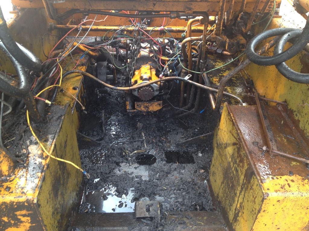
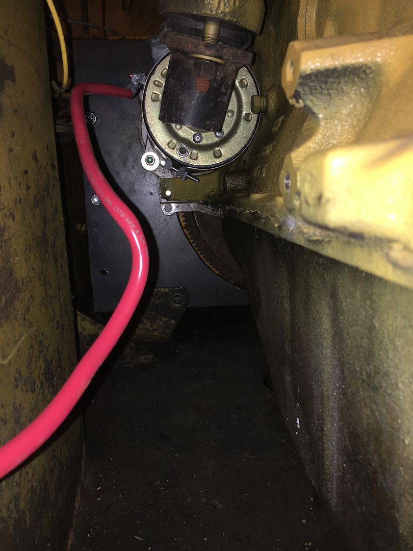
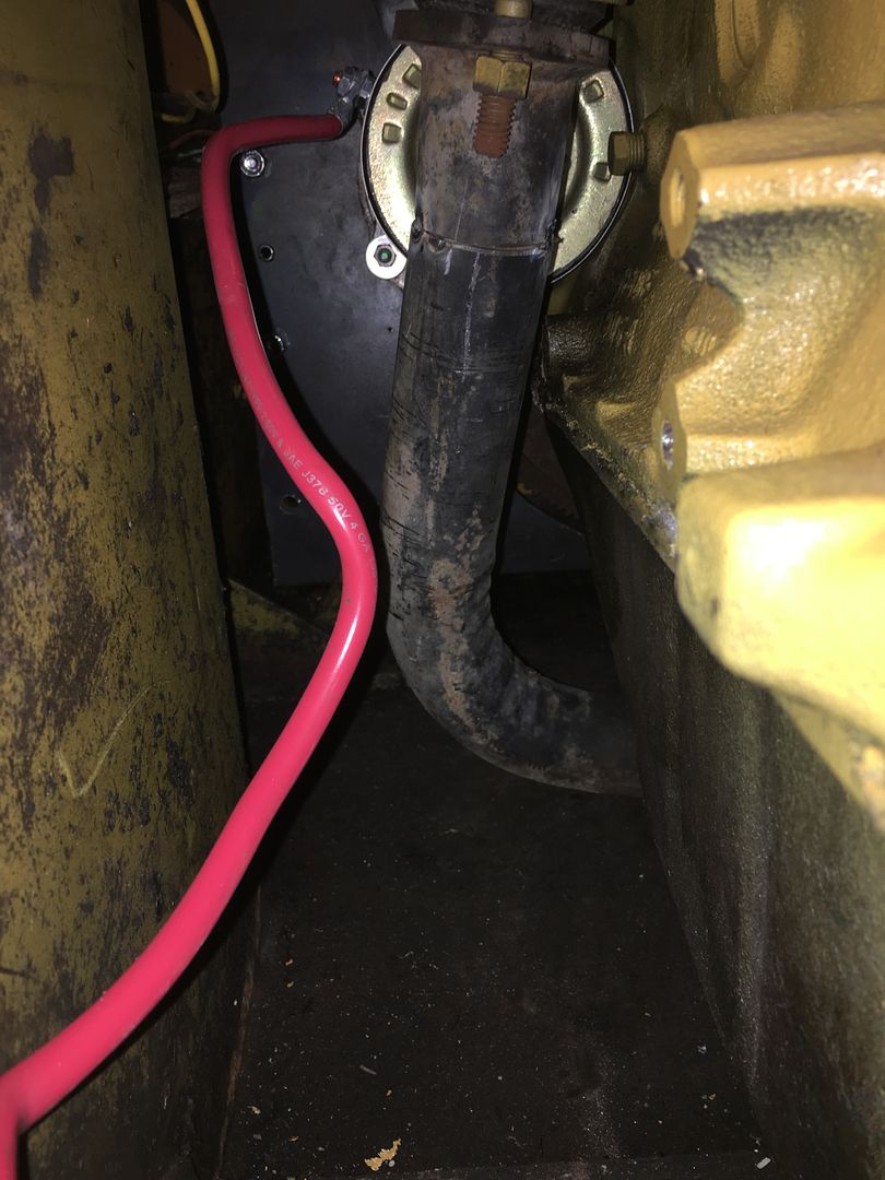
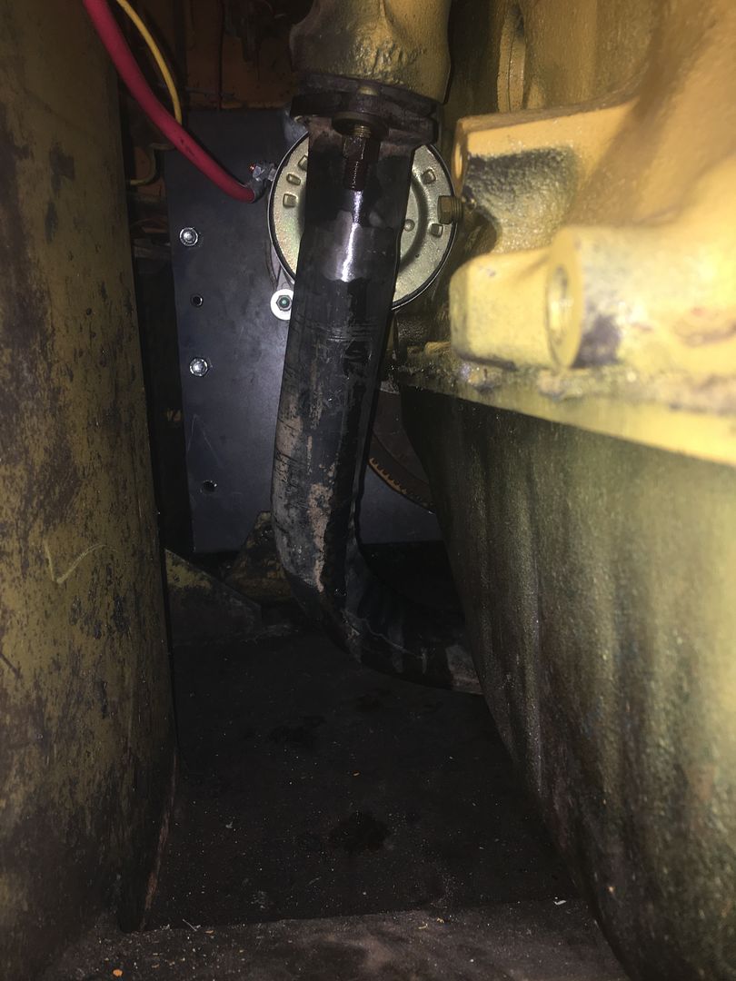
I eventually got to a point where I could see color on the pump and the steel lines on the right hnad side, but the wiring is complete trash.
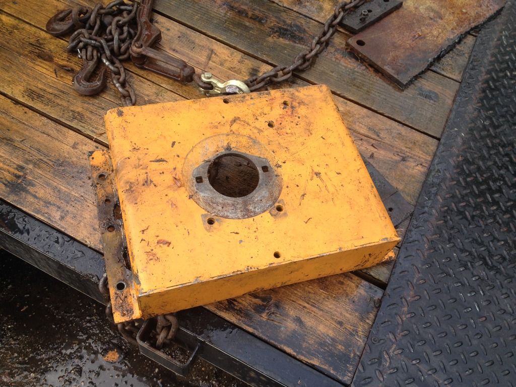
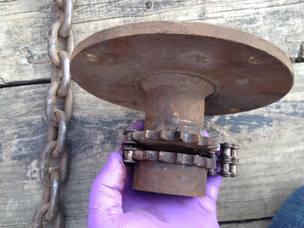
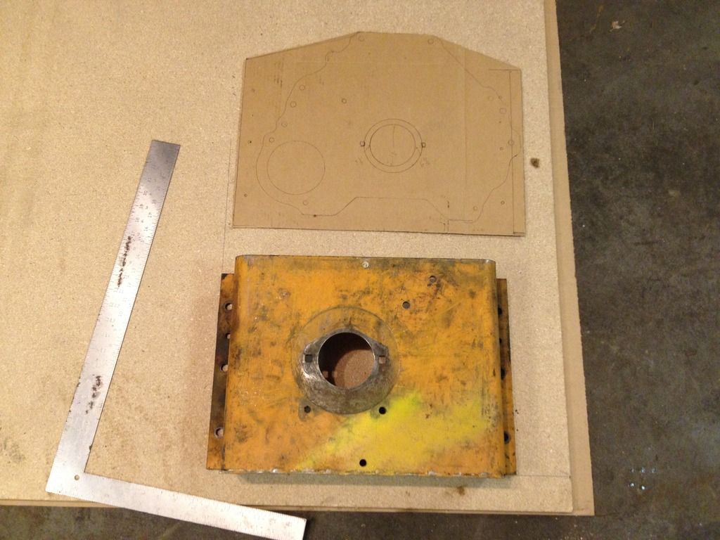
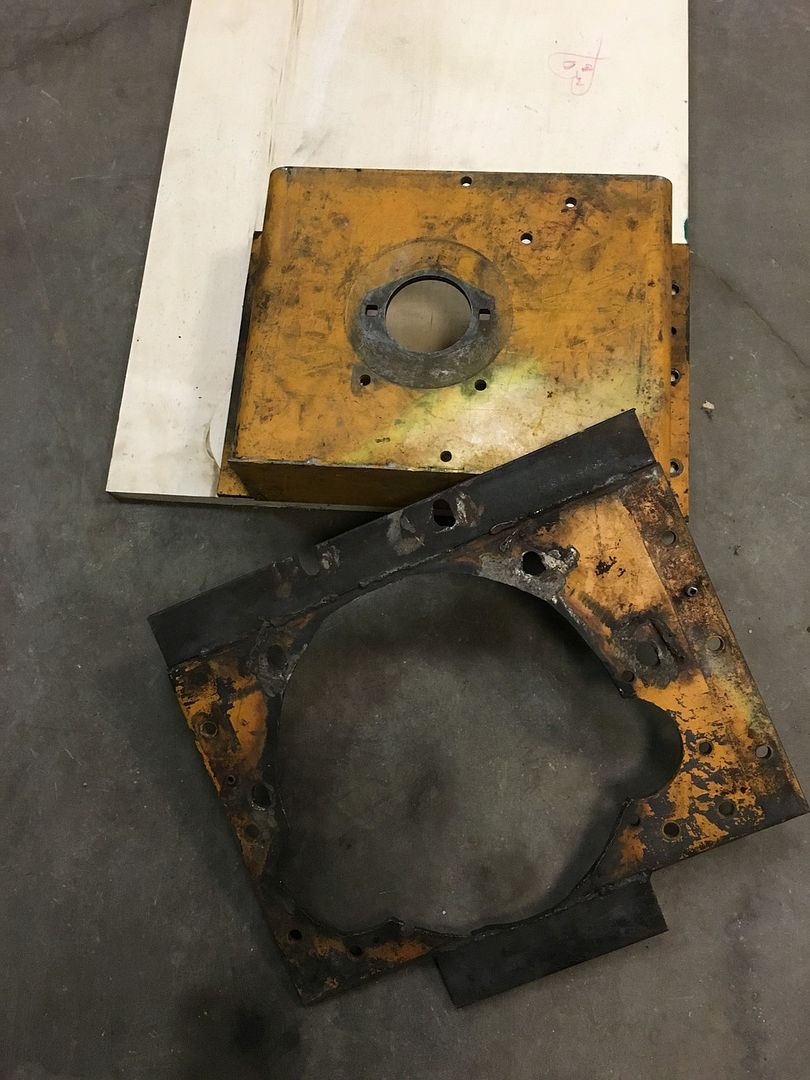
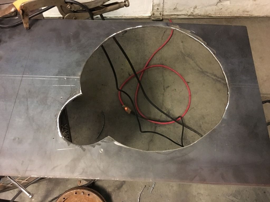
This is the pump side of the adapter box that mounts between the main pump and the motor.
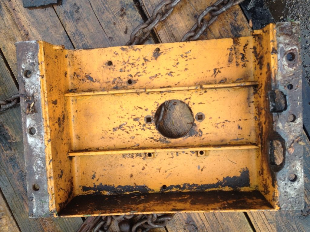
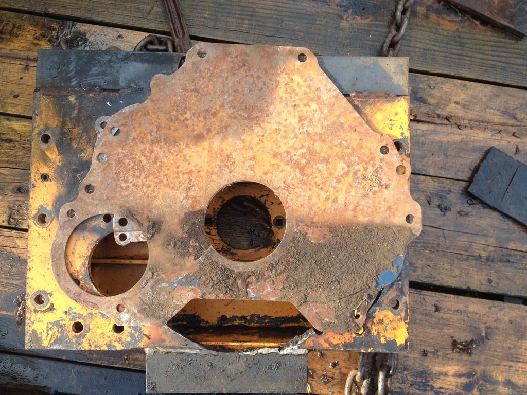
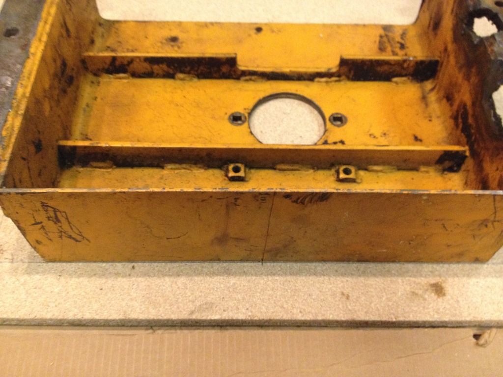
Here is the inside of that same box, pay attention to the lovely torch marks on the right hand side, that is where the Previous Owner (PO) clearanced the box to make room for the 2.5L motor swap/repower.
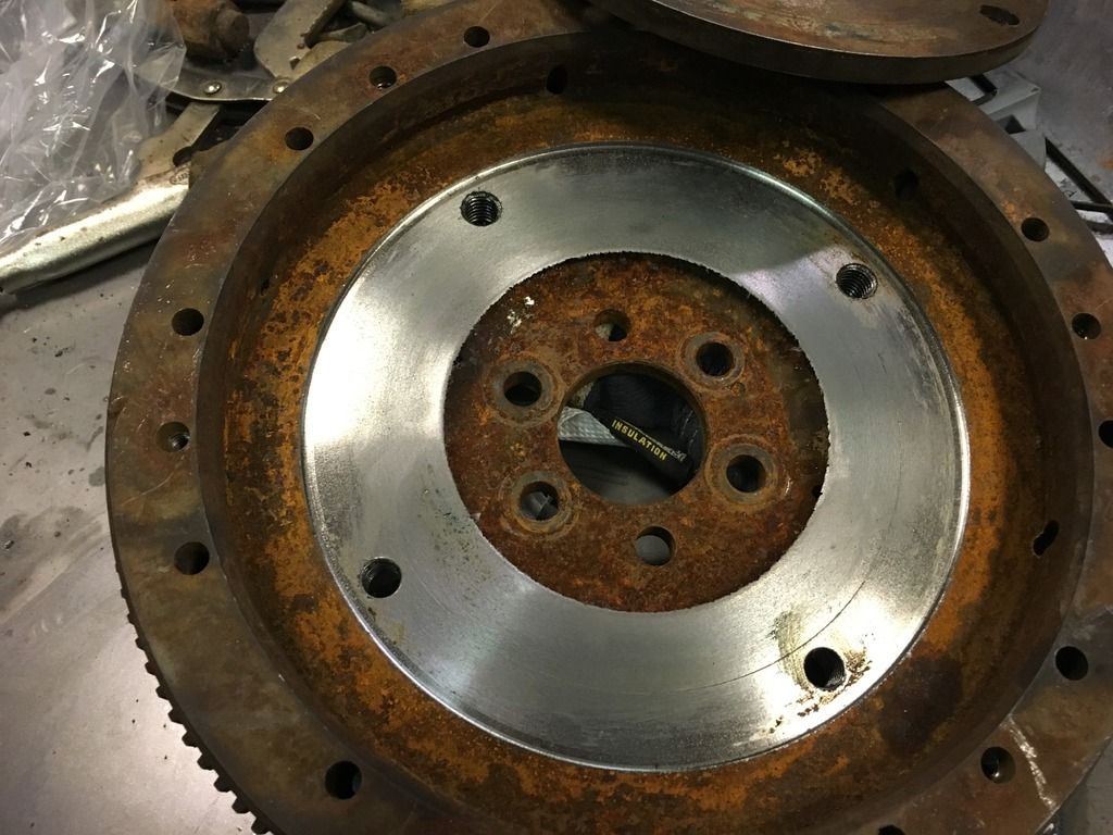
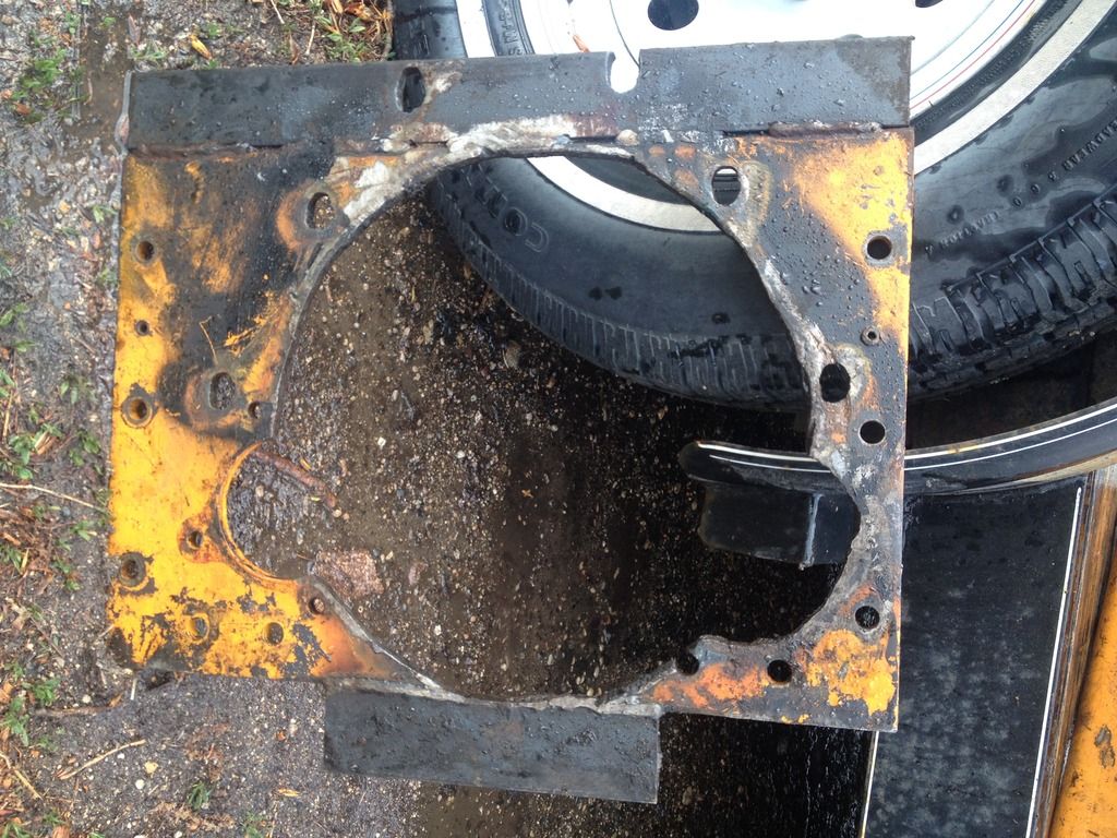
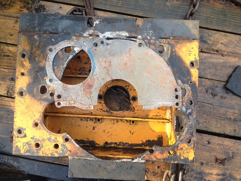
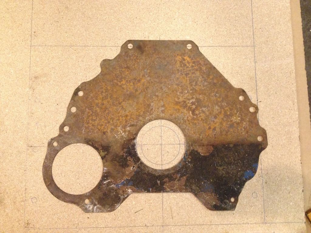
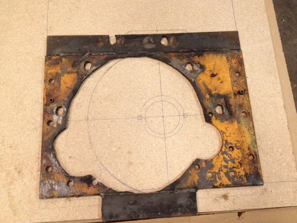
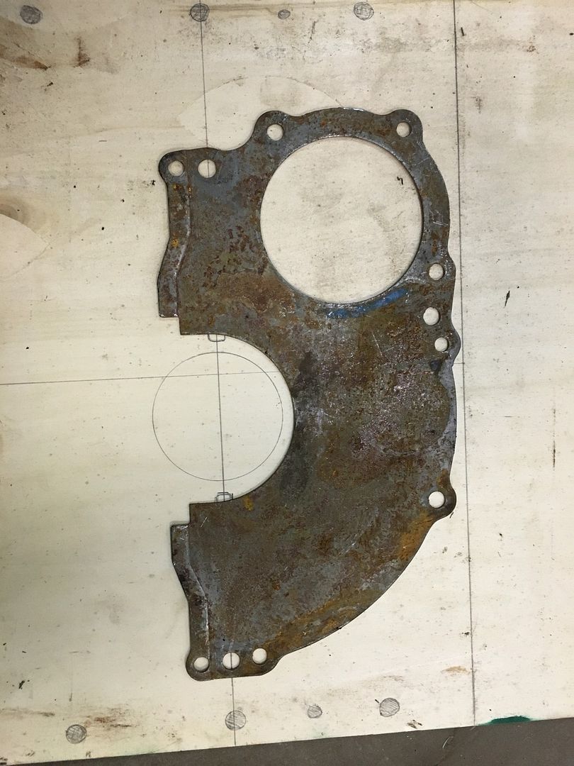
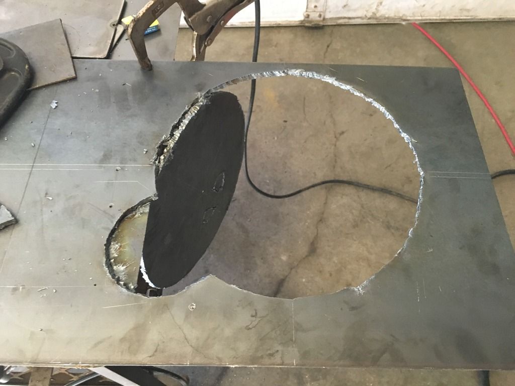
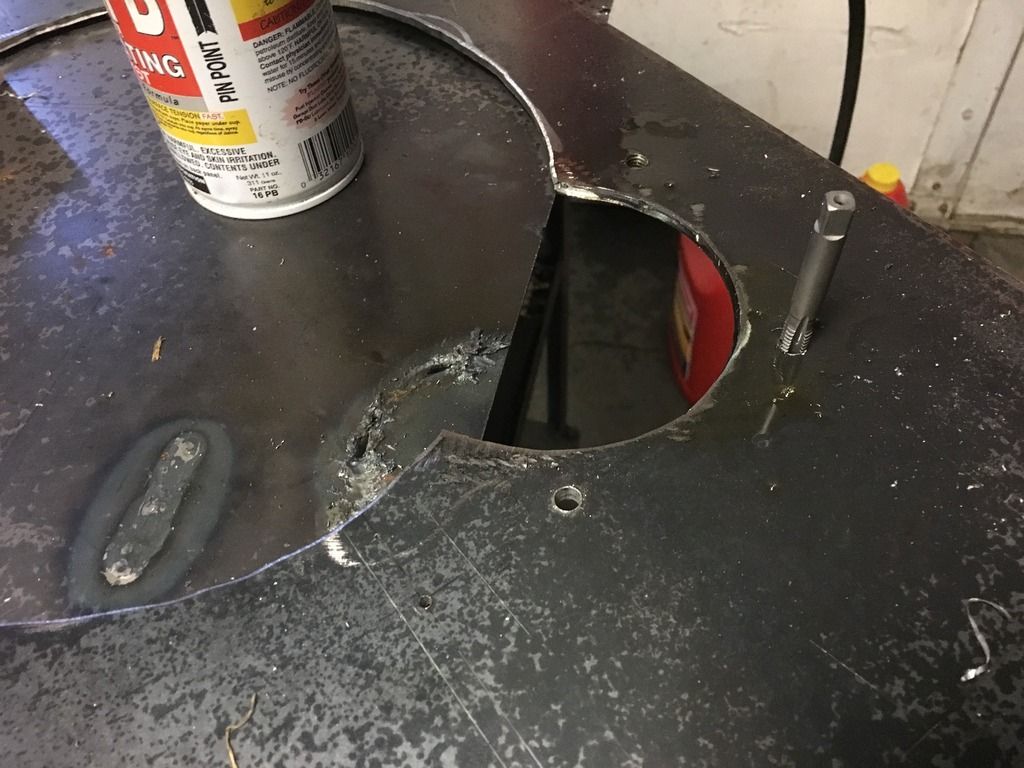
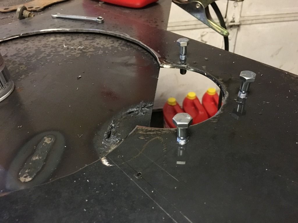
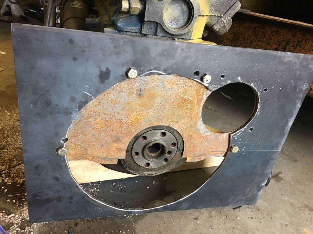
Next up, we have the bellhousing adapter plate, this is a real beauty, the owner torched the bellhousing hole larger, and used the same torch to create the new bellhousing bolt holes, he slotted them for extra clearance. He also had to add material to the top and bottom of the adapter, the bottom because he torched through it, and the top to capture the bellhousing bolts.
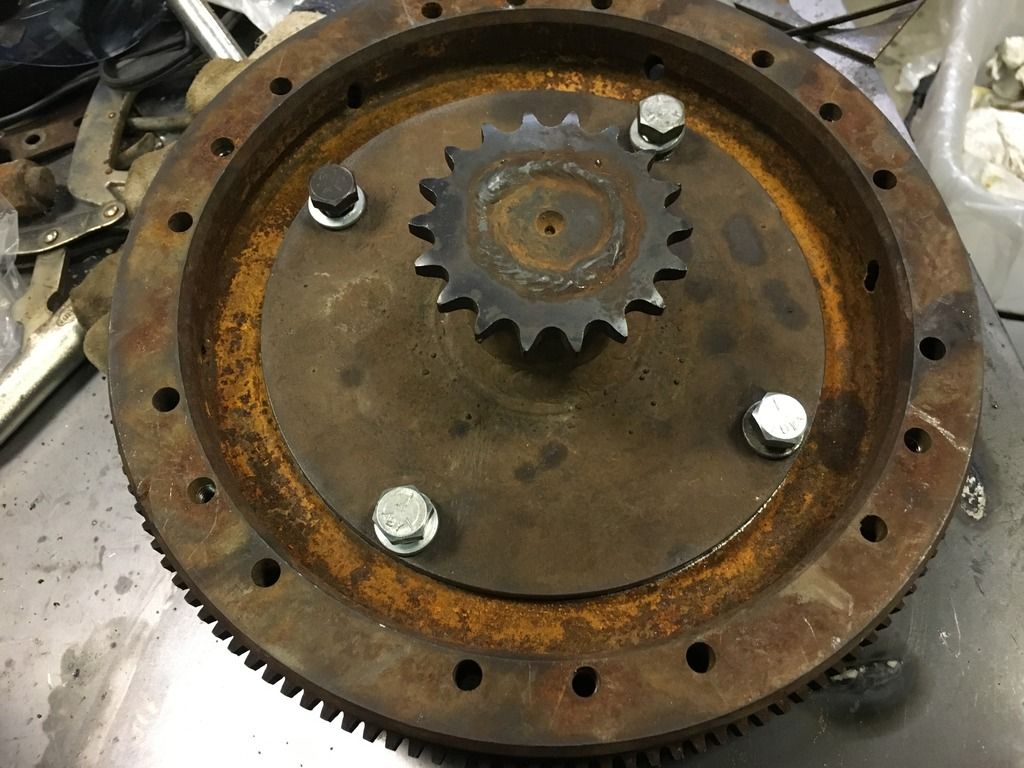
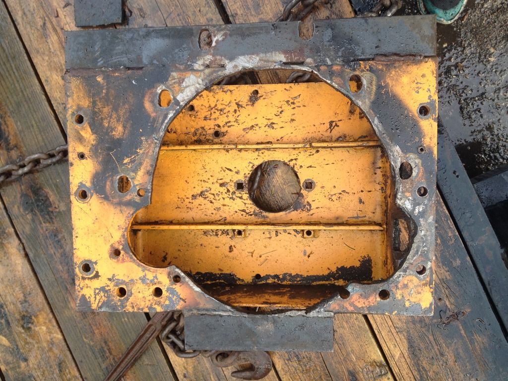
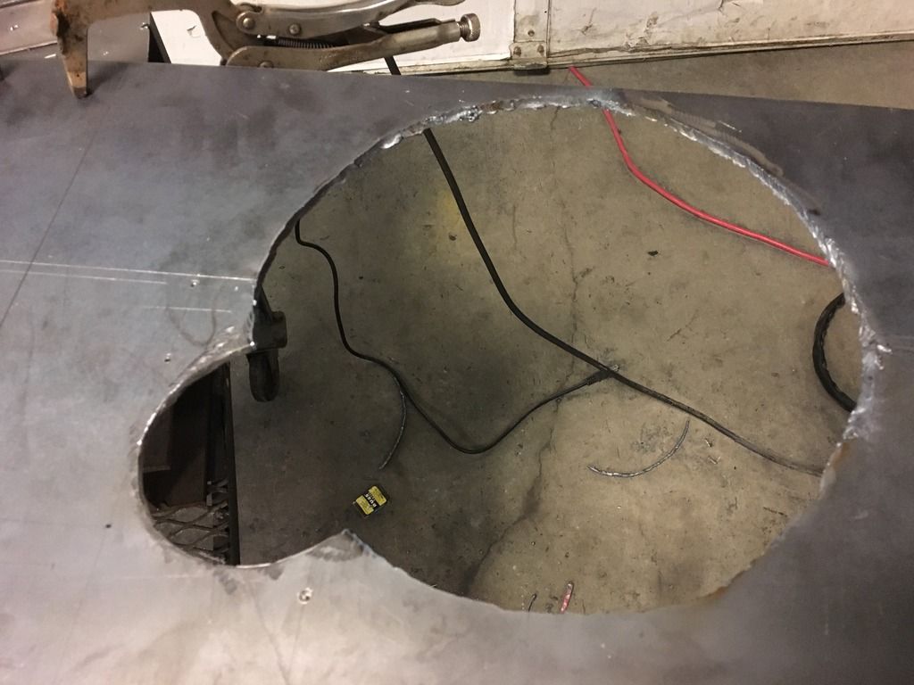
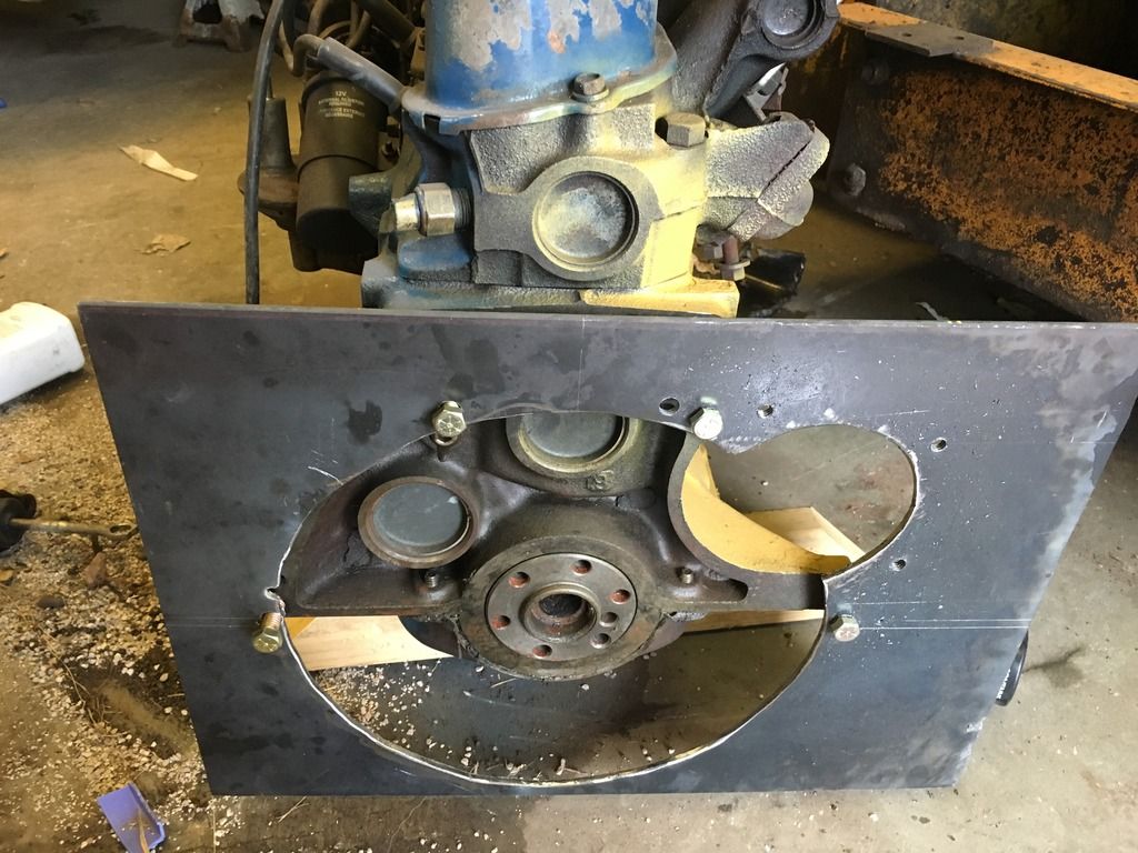
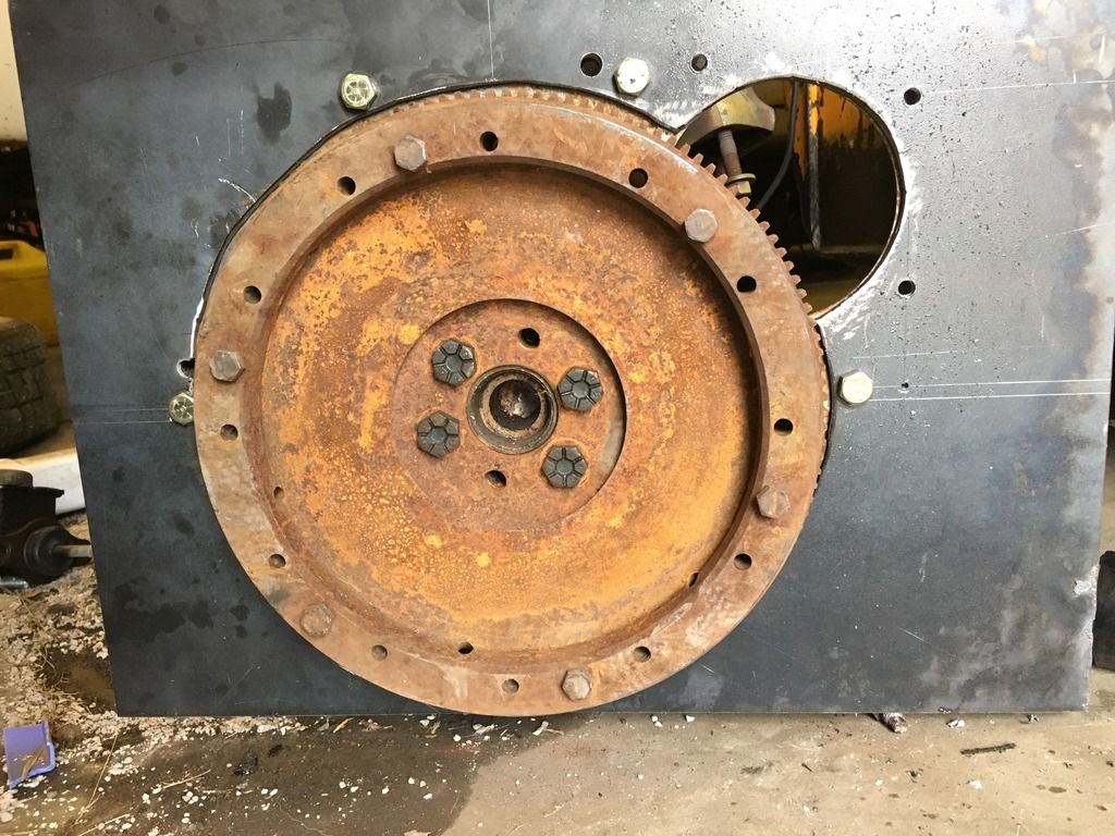
This is how the adapter box looks when the parts are set together, the back of the motor bellhousing would bolt to the nearest plate, and the hydraulic pump to the rear plate. You can also see the torched view holes on the right side.
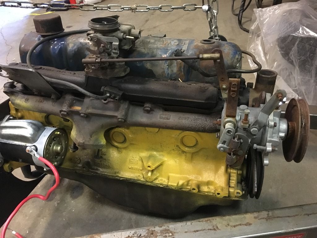
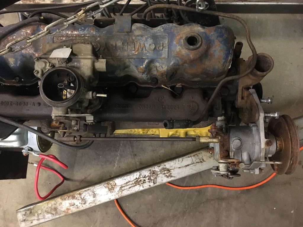
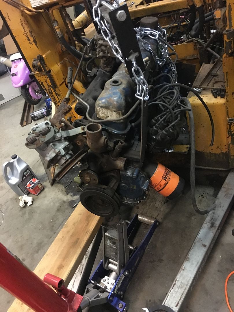
So at this point, I don't have the original motor, I don't have the last repowered motor (gm 2.5L); what I do have is a collection of Ford inline sixes (144/170/200/250/240/300). The 240 and 300 are a bit much for a machine of thise size, after all this thing was designed for a 30hp motor. The 144 (2.5L) doesn't run, but the 170 2.8L does, as do all of the 200's that I have. So I'm going to use the 170, it is out of a 1970 Maverick. I bought it for $20 off craigslist a couple years ago from a guy who did a v8 swap.
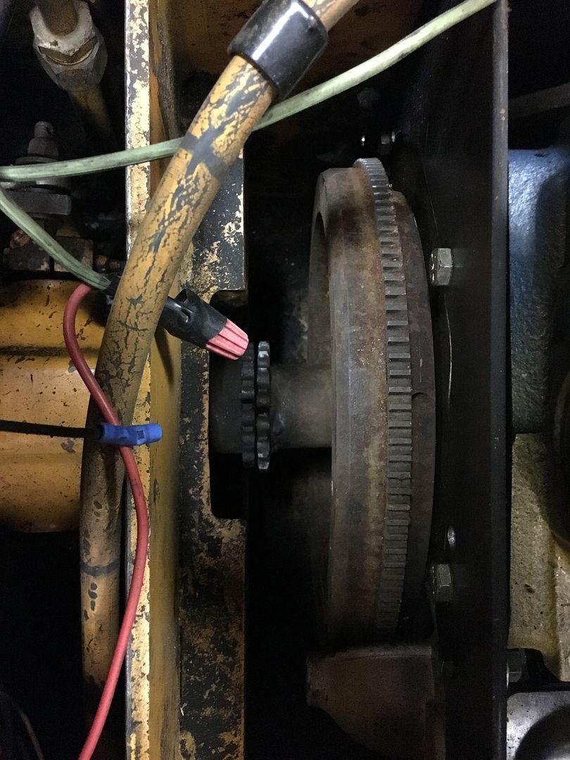
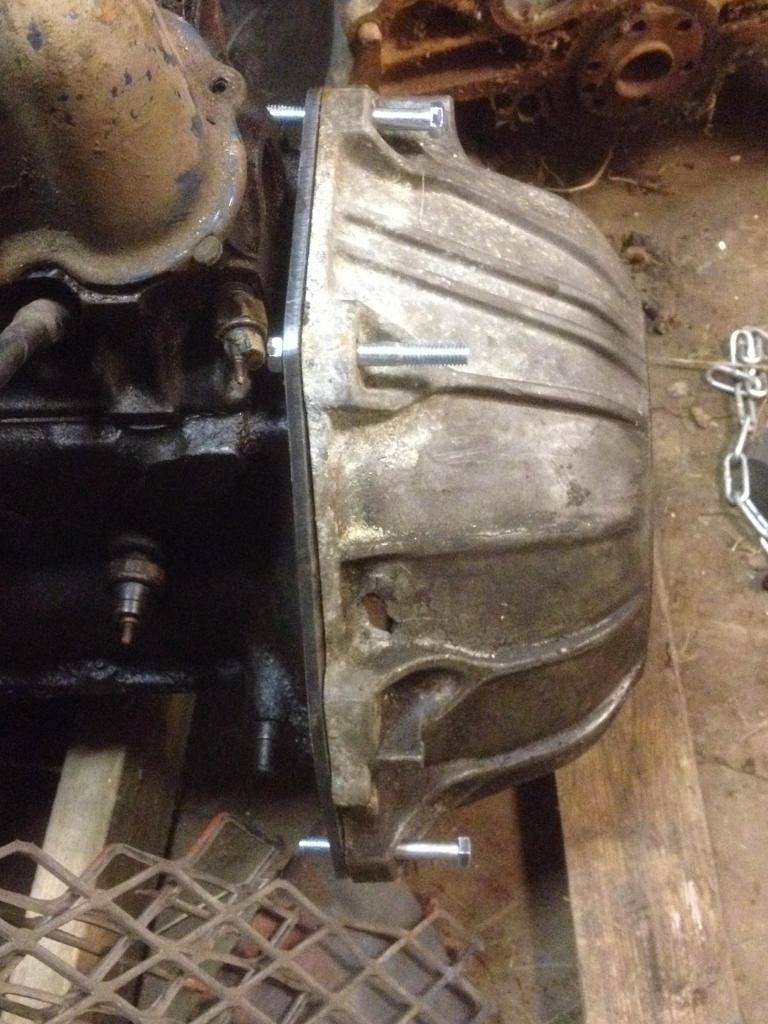
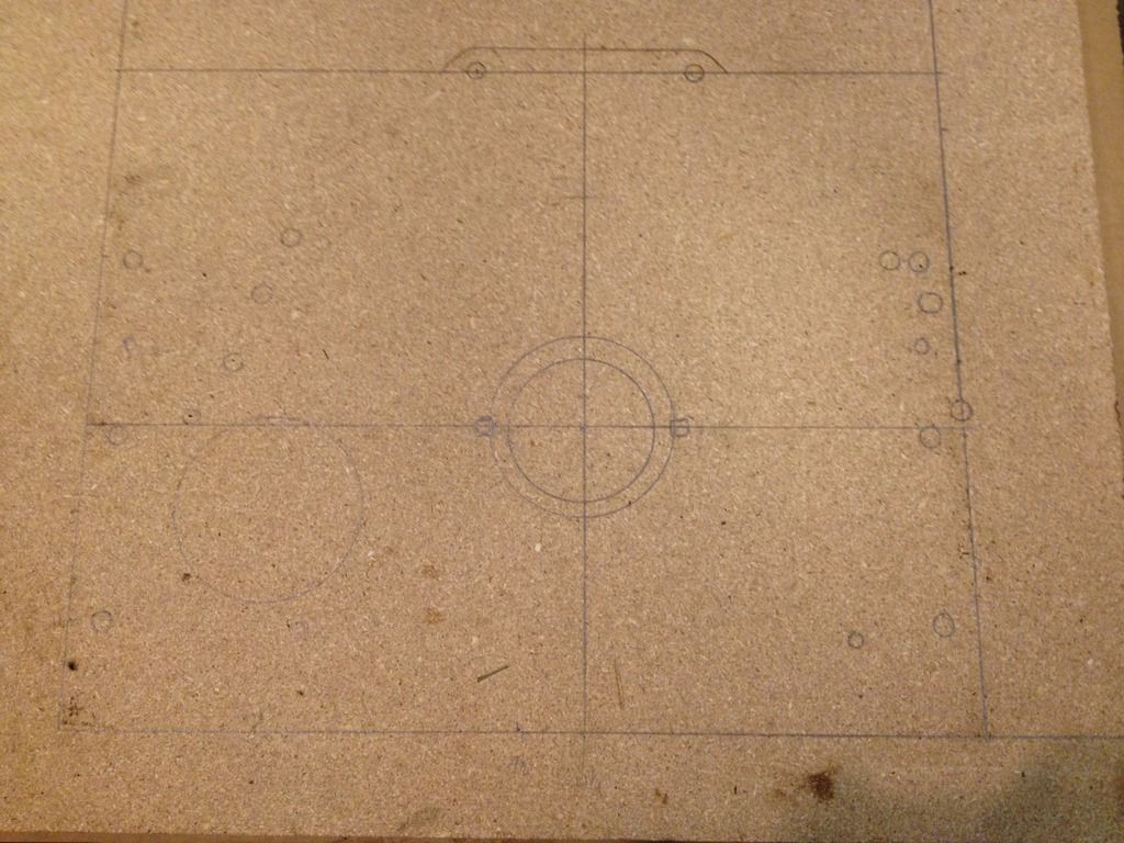
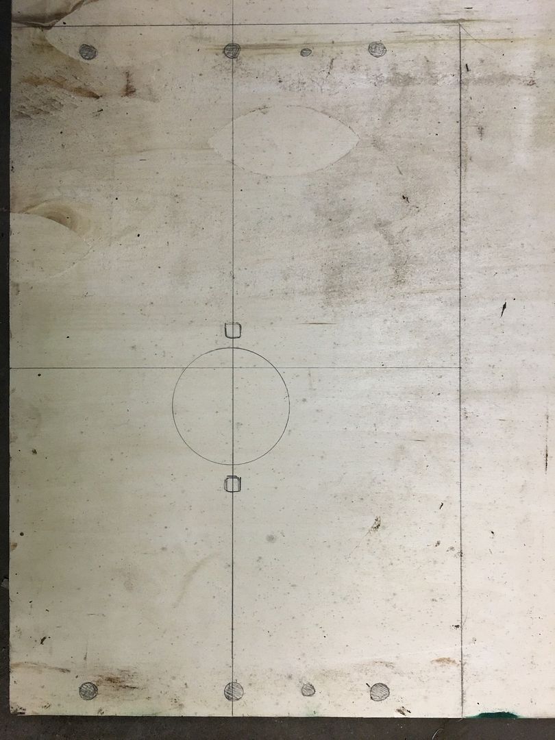
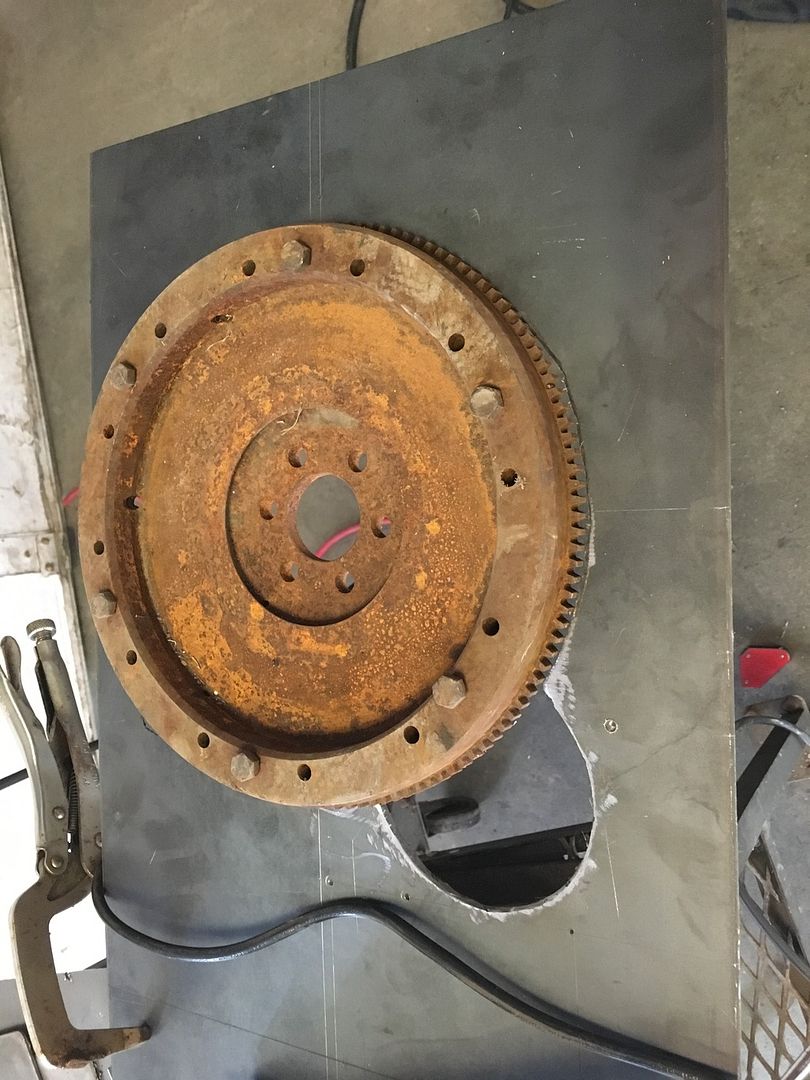
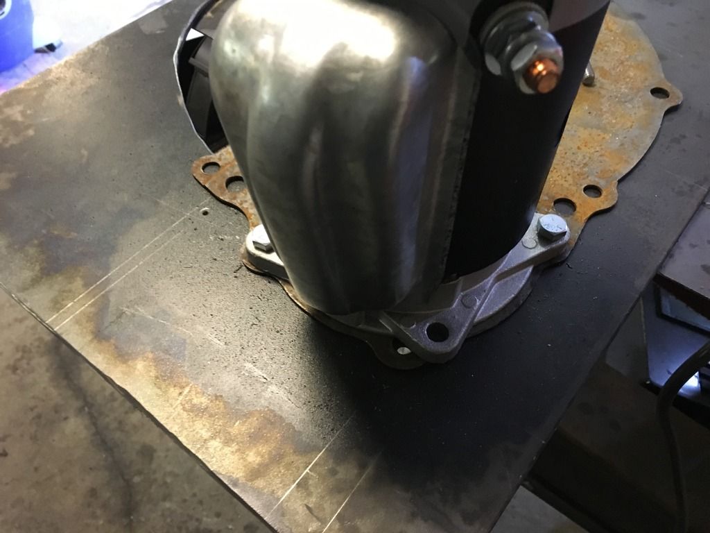
This is what it would look like if I could use the small i6 bellhousing.
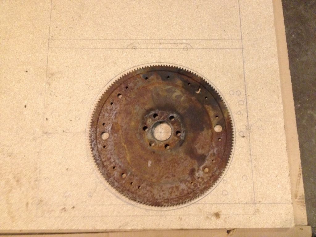
Unfortunately for me, Ford never made a flexplate with a ring gear attached, and I don't have any flywheels for the small 6.
Luckily for me, I am a member of a Ford 6 cylinder website and late last year, I created an adapter that lets me use a small 6 cylinder motor on a Small Block Ford (SBF) bellhousing.
Ford Small 6 to SBF Adapter -- Photobucket Gallery
This picture shows the small 6 block spacer plate at the top, my conversion/adapter in the middle, and a stock SBF block spacer plate at the bottom.
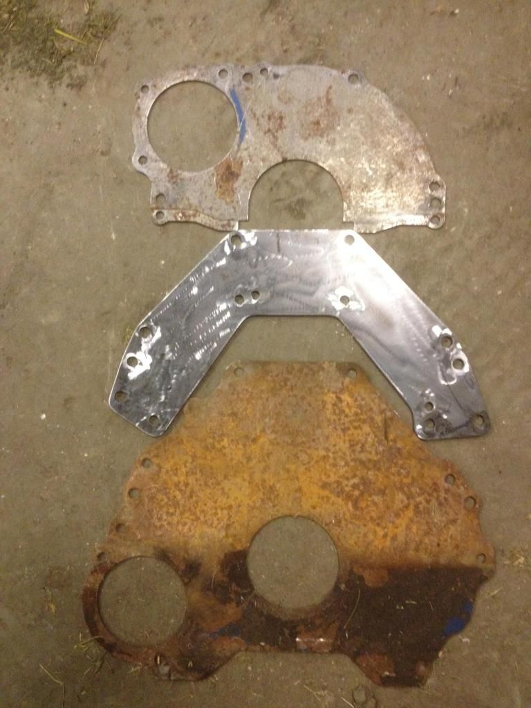
When you bolt the adapter to the block, you can then use any SBF transmission behind a small 6.
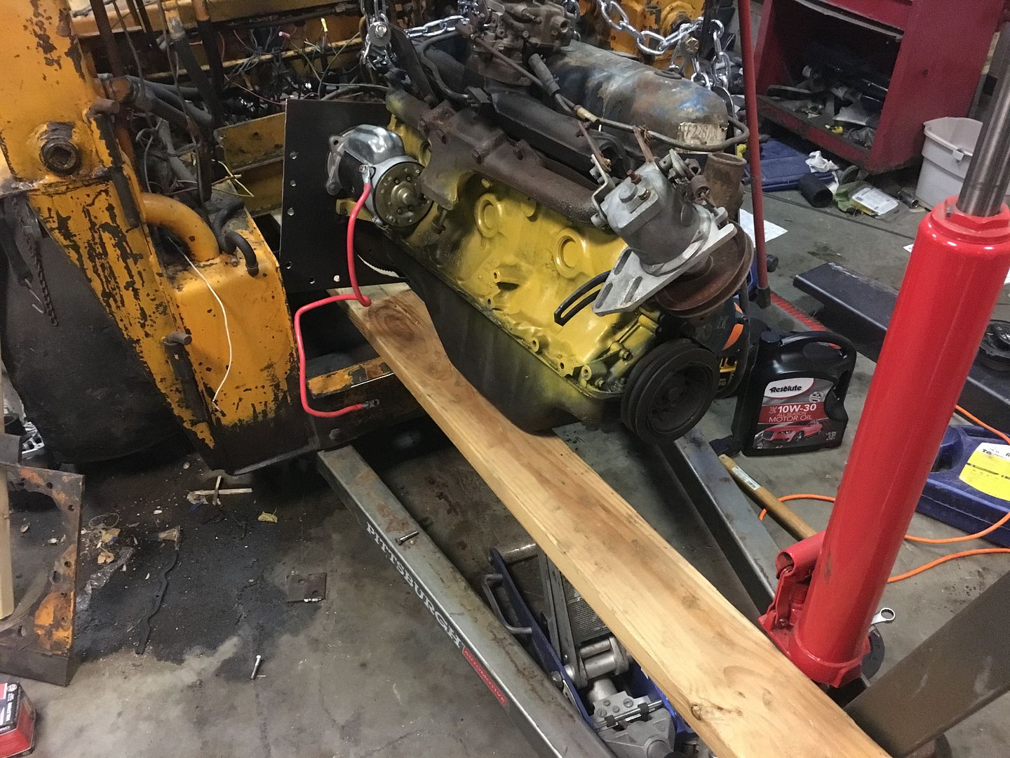
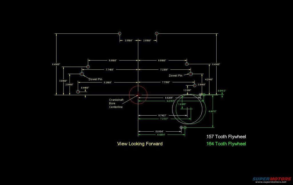
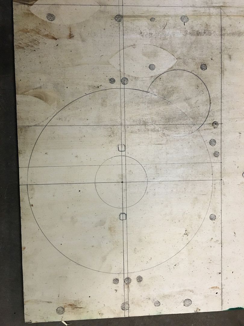
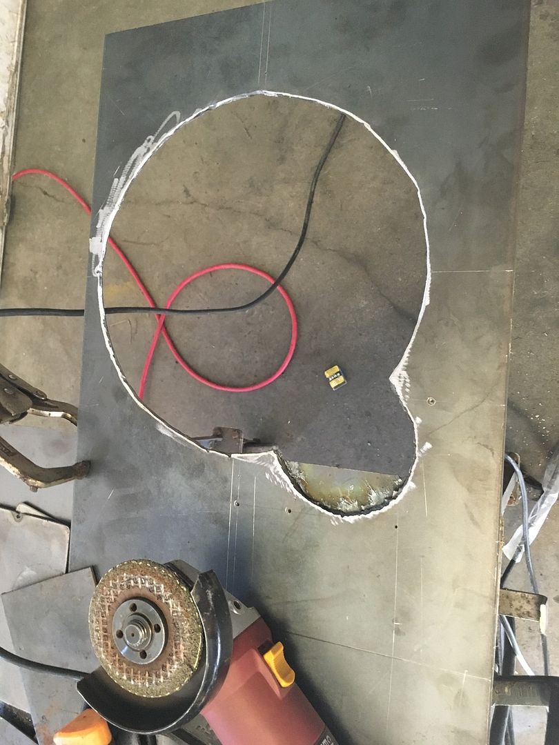
So with that in my arsenal of parts, I am going to use a standard SBF bellhousing pattern for the engine side of the Case adapter box.
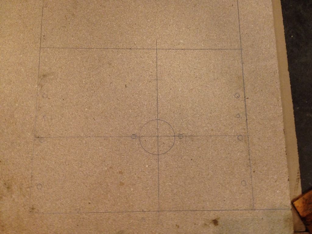
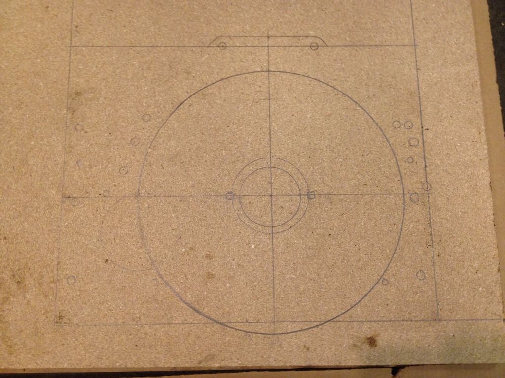
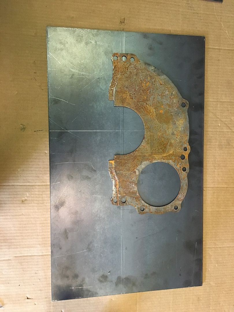
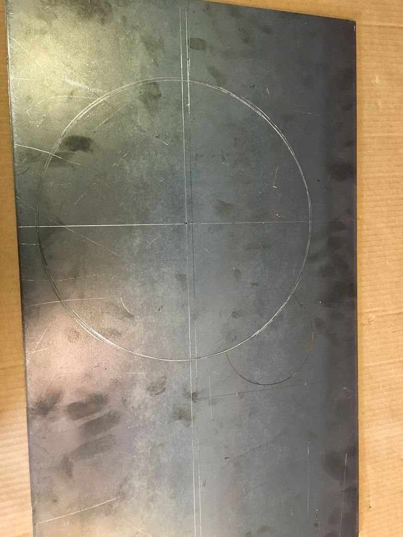
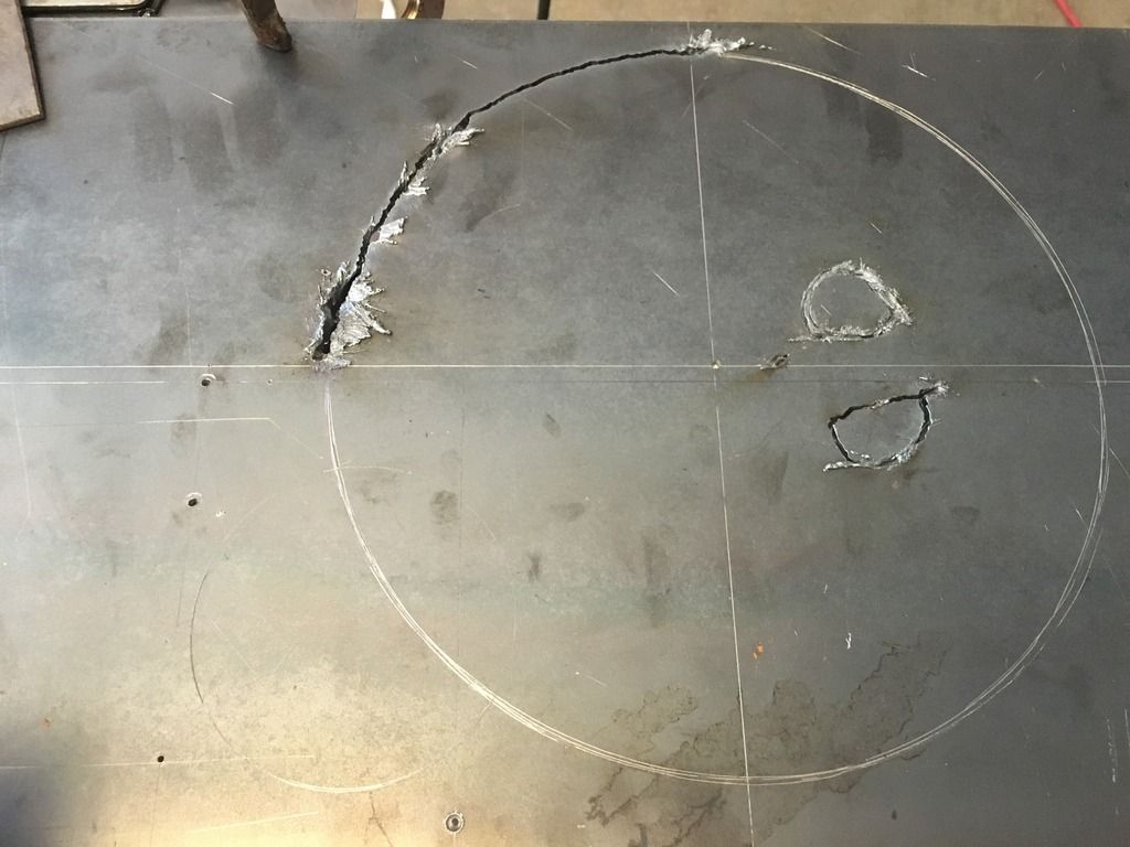
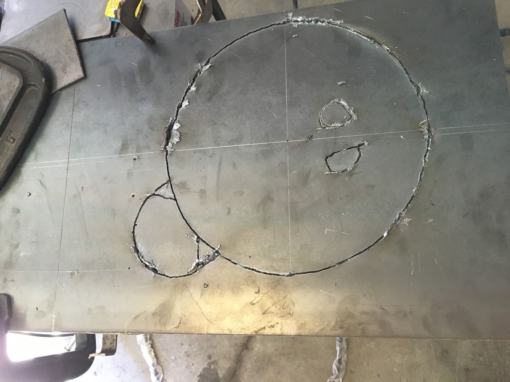
It will fit roughly like this, I'll have to buy a piece of 3/8" and I'll make a new adapter.
It won't be quite as elegant as the small 6 pattern would have been, but it will allow me to swap in any of my i6 motors if I should happen to have serious motor problems.
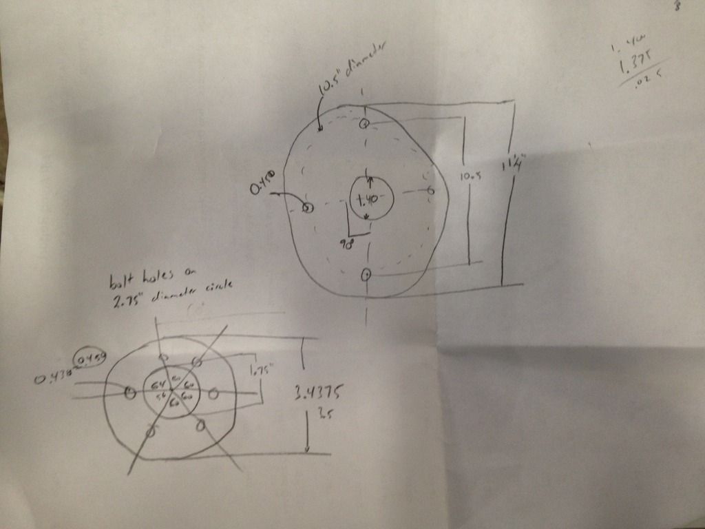
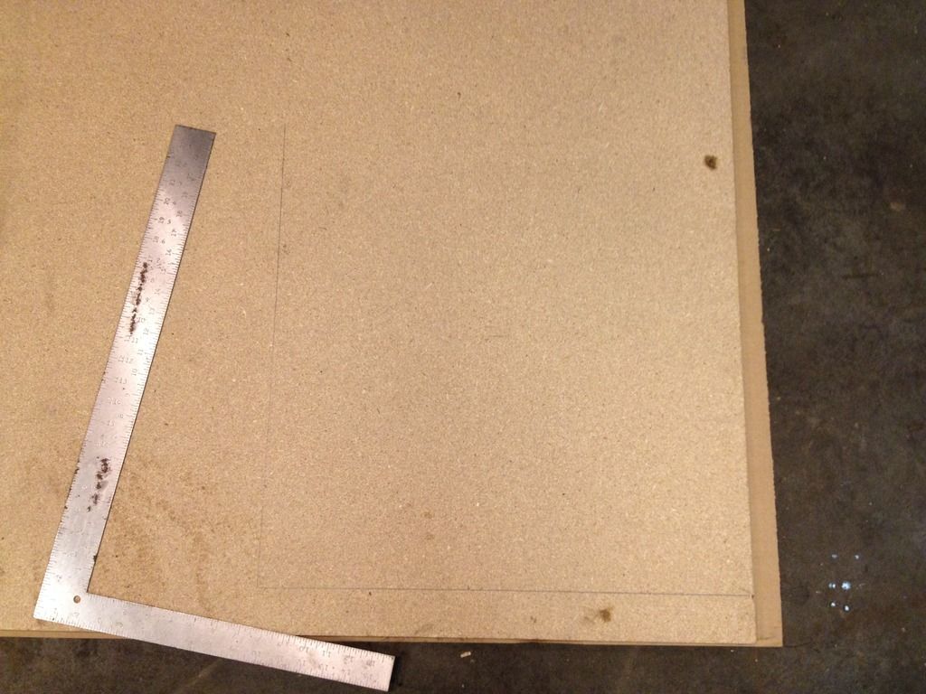
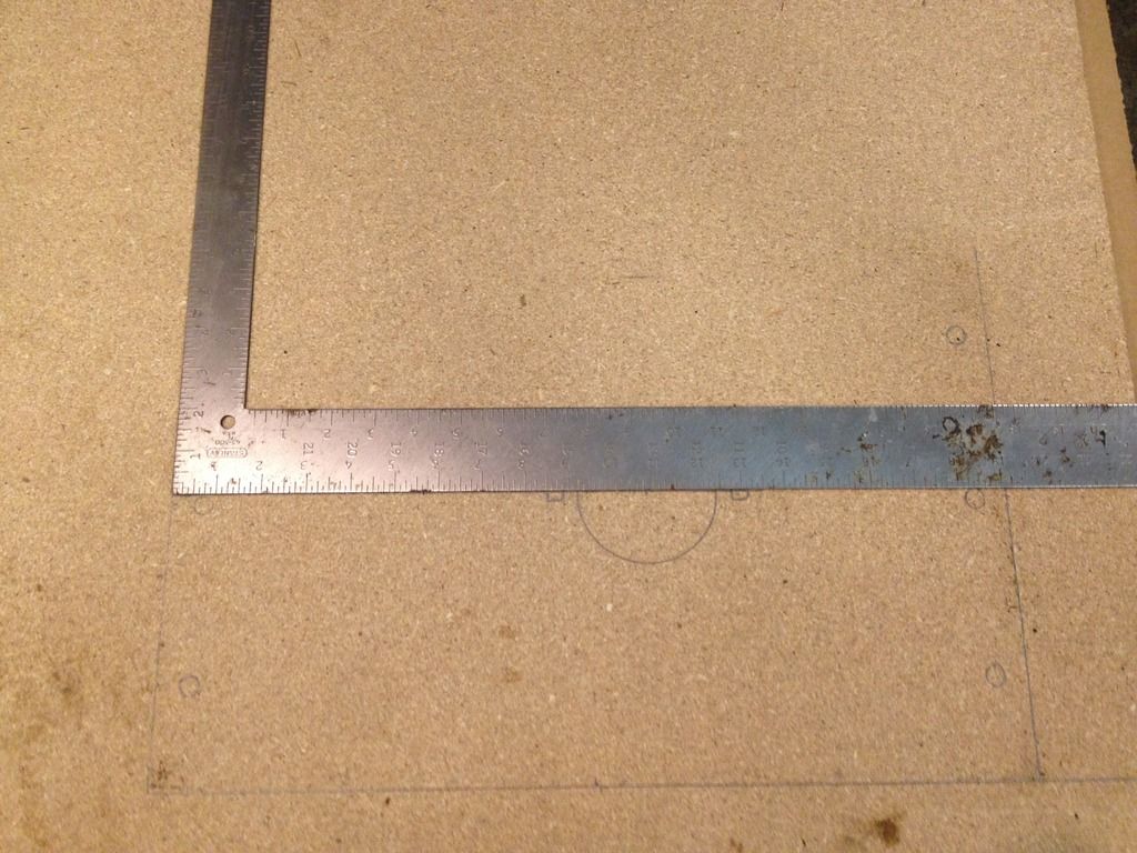
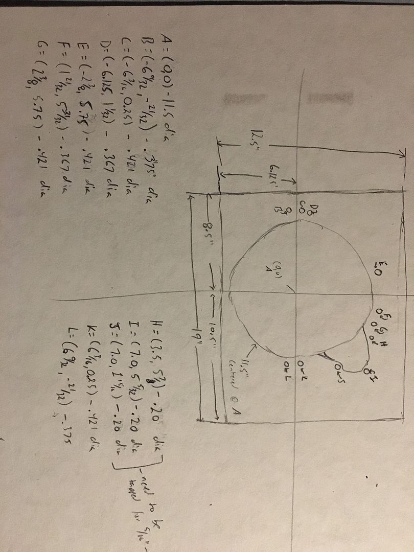
How about some important measurements.
The stock Adapter box is 5" deep, 16" wide 12" tall.
My desired repower motor is 31" long from bellhousing to harmonic balancer/waterpump.
My so my entire installed length will be 36", and eventually I'll have to figure out where I'm putting a radiator.
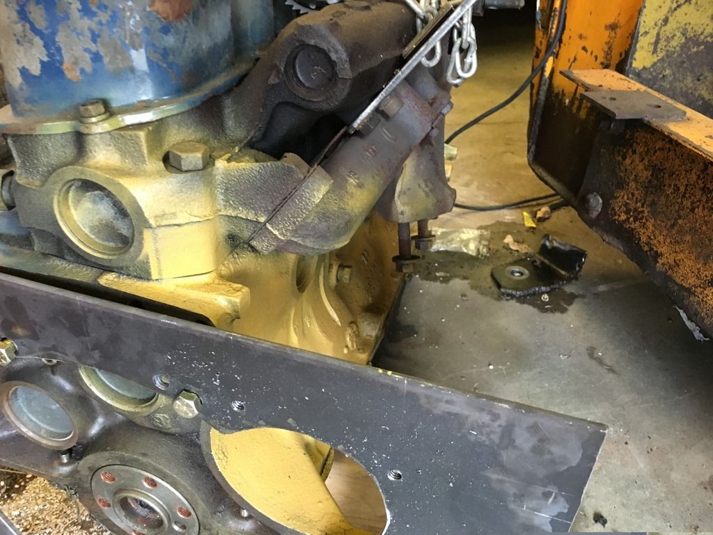
For what its worth, 36" puts me right about here.
Giving me about an inch and a quarter behind these brackets that the previous owner added.
Which is almost enough space...
If I didn't also have to figure out where to put a radiator.
Although, I'm not terribly worried about that, the previous owner already provided the idea for what I'd need to do, he created some extension plates out of 3/8" steel to move the rear swing door out for more clearance.
You can see them in this picture, they are black and kind of ugly.
I've got more thoughts and ideas. But I also need lunch..
Any comments, suggestions, or critisism is welcomed.
It was parked when the 2.5L started smoking and knocking, and had been parked for an unknown number of years. My Dad started tearing it down and has a couple 2.5L GM motors at his place and had planned on simply replacing the existing motor with one of the same. He started tearing into it and found that the brakes needed to be rebuilt also, so he tore those apart as well. And then in an unfortunate turn, his health prevented him from reassembling it. So after sitting at his house for almost 2 years with no motor, and the brakes apart; I loaded it up on a trailer and brought it to my house.
The engine bay virtually void of anything usable, wiring harness is a nightmare, nothing but a rats nest of black tape and wire nuts. This picture was taken after I started pressure washing out the 1-3" of garbage from the bottom.
I eventually got to a point where I could see color on the pump and the steel lines on the right hnad side, but the wiring is complete trash.
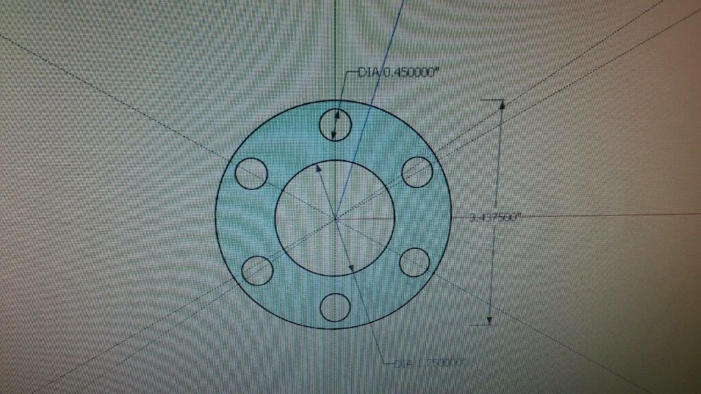
This is the pump side of the adapter box that mounts between the main pump and the motor.
Here is the inside of that same box, pay attention to the lovely torch marks on the right hand side, that is where the Previous Owner (PO) clearanced the box to make room for the 2.5L motor swap/repower.
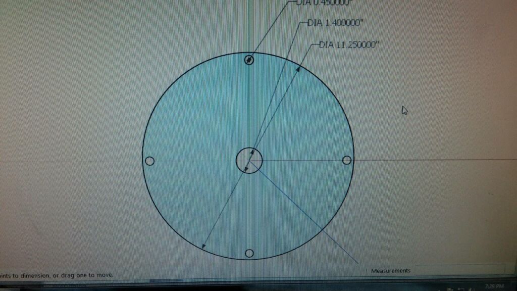
Next up, we have the bellhousing adapter plate, this is a real beauty, the owner torched the bellhousing hole larger, and used the same torch to create the new bellhousing bolt holes, he slotted them for extra clearance. He also had to add material to the top and bottom of the adapter, the bottom because he torched through it, and the top to capture the bellhousing bolts.
This is how the adapter box looks when the parts are set together, the back of the motor bellhousing would bolt to the nearest plate, and the hydraulic pump to the rear plate. You can also see the torched view holes on the right side.
So at this point, I don't have the original motor, I don't have the last repowered motor (gm 2.5L); what I do have is a collection of Ford inline sixes (144/170/200/250/240/300). The 240 and 300 are a bit much for a machine of thise size, after all this thing was designed for a 30hp motor. The 144 (2.5L) doesn't run, but the 170 2.8L does, as do all of the 200's that I have. So I'm going to use the 170, it is out of a 1970 Maverick. I bought it for $20 off craigslist a couple years ago from a guy who did a v8 swap.
This is what it would look like if I could use the small i6 bellhousing.
Unfortunately for me, Ford never made a flexplate with a ring gear attached, and I don't have any flywheels for the small 6.
Luckily for me, I am a member of a Ford 6 cylinder website and late last year, I created an adapter that lets me use a small 6 cylinder motor on a Small Block Ford (SBF) bellhousing.
Ford Small 6 to SBF Adapter -- Photobucket Gallery
This picture shows the small 6 block spacer plate at the top, my conversion/adapter in the middle, and a stock SBF block spacer plate at the bottom.
When you bolt the adapter to the block, you can then use any SBF transmission behind a small 6.
So with that in my arsenal of parts, I am going to use a standard SBF bellhousing pattern for the engine side of the Case adapter box.
It will fit roughly like this, I'll have to buy a piece of 3/8" and I'll make a new adapter.
It won't be quite as elegant as the small 6 pattern would have been, but it will allow me to swap in any of my i6 motors if I should happen to have serious motor problems.
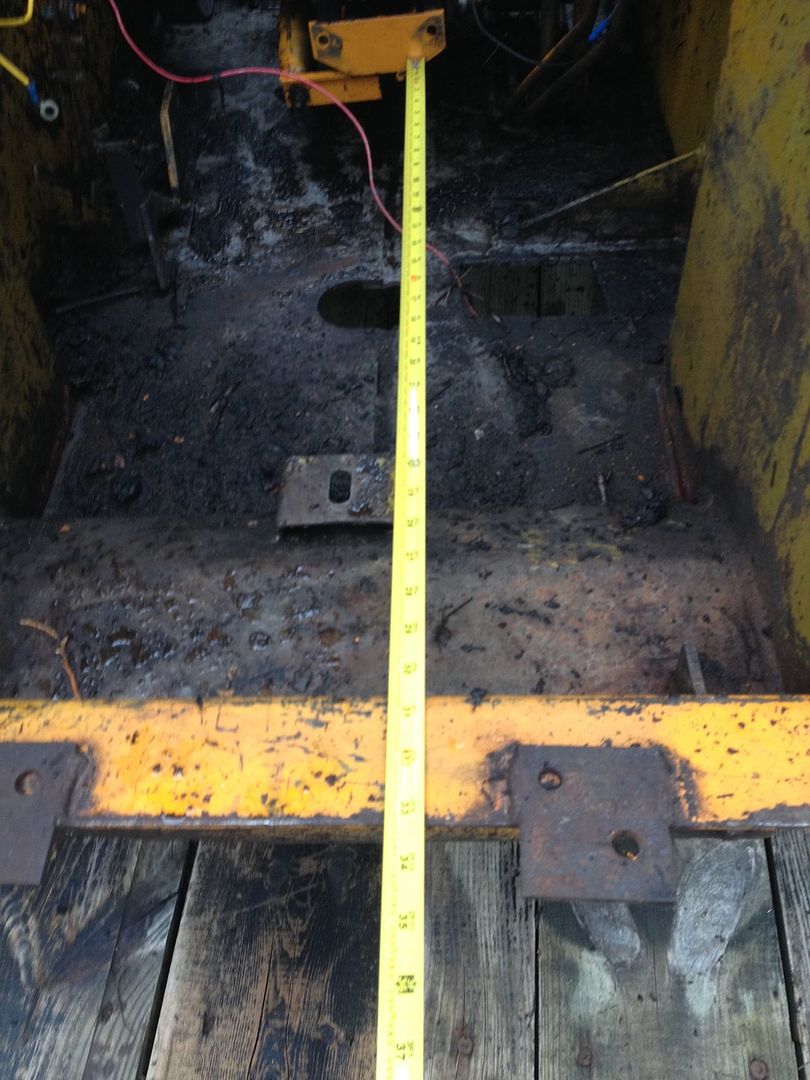
How about some important measurements.
The stock Adapter box is 5" deep, 16" wide 12" tall.
My desired repower motor is 31" long from bellhousing to harmonic balancer/waterpump.
My so my entire installed length will be 36", and eventually I'll have to figure out where I'm putting a radiator.
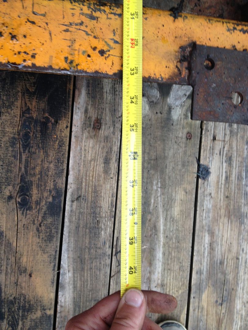
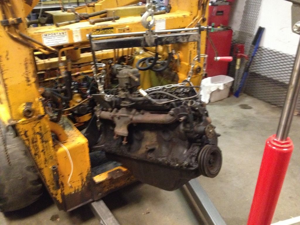
For what its worth, 36" puts me right about here.
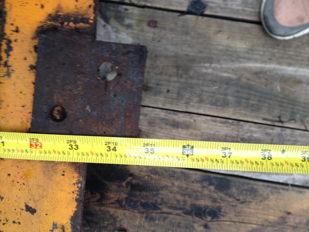
Giving me about an inch and a quarter behind these brackets that the previous owner added.
Which is almost enough space...
If I didn't also have to figure out where to put a radiator.
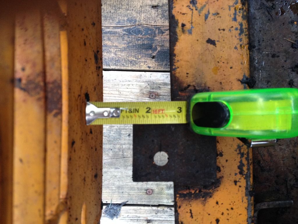
Although, I'm not terribly worried about that, the previous owner already provided the idea for what I'd need to do, he created some extension plates out of 3/8" steel to move the rear swing door out for more clearance.
You can see them in this picture, they are black and kind of ugly.
I've got more thoughts and ideas. But I also need lunch..
Any comments, suggestions, or critisism is welcomed.
")