630 Skid-By-Wire

Help Support SkidSteer Forum:

peebeeaitch

Well-known member
Joined
Dec 3, 2012
Messages
115
So I got going on a new project for the little machine the other day.
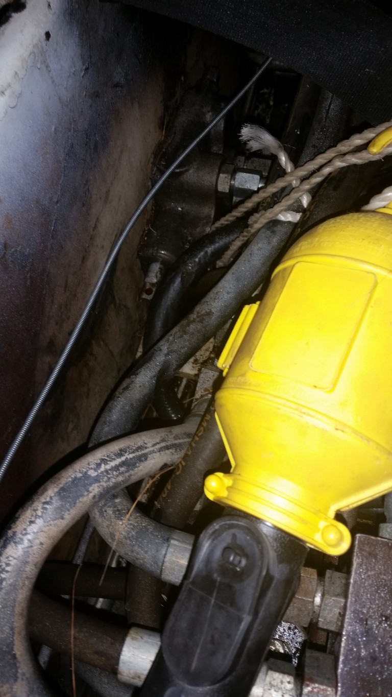
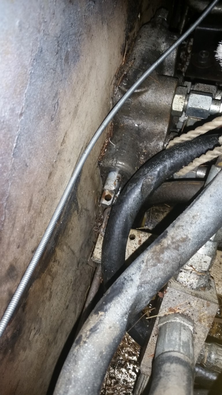
In my Prestolite post there is a mention of those infuriating control valve spools. My machine was stuck on the driveway for the entire winter of one of the four coldest winters in Illinois history. The cause was a combination of frustration, ignorance, haste, incompetence and misplaced enthusiasm. The eventual restarting of the machine had much to do with this forum.
Then, to add insult to injury, a colleague offered to move a very heavy piece of equipment I purchased with his Cat 263B. After doing the difficult stuff, he "suggested" I move the machine back to the trailer for him. When I'd secured myself inside he nonchalantly told me that once I had used the electronic controls I would never be able to use my machine again.
He was partly correct. The side sticks are really cool. I have plenty of slop in my foot pedals, and the control is anything but. More of a digital raise/lower at fastest possible rate. There is a bit of bind between the left and right yankem which results in me being able to drive in a straight line with my left hand on the left stick and my right holding a beverage.
I was insulted so I started shopping around for proportional hydraulic valves. Wow. Was I brought down to earth quickly: there are the quality devices (things one would trust with one's life, or fortune), one step down the stuff that doesn't have the name, but looks the same, and then the stuff which looks the same but costs 1/10th. And the 1/10th was 10x more than the budget.
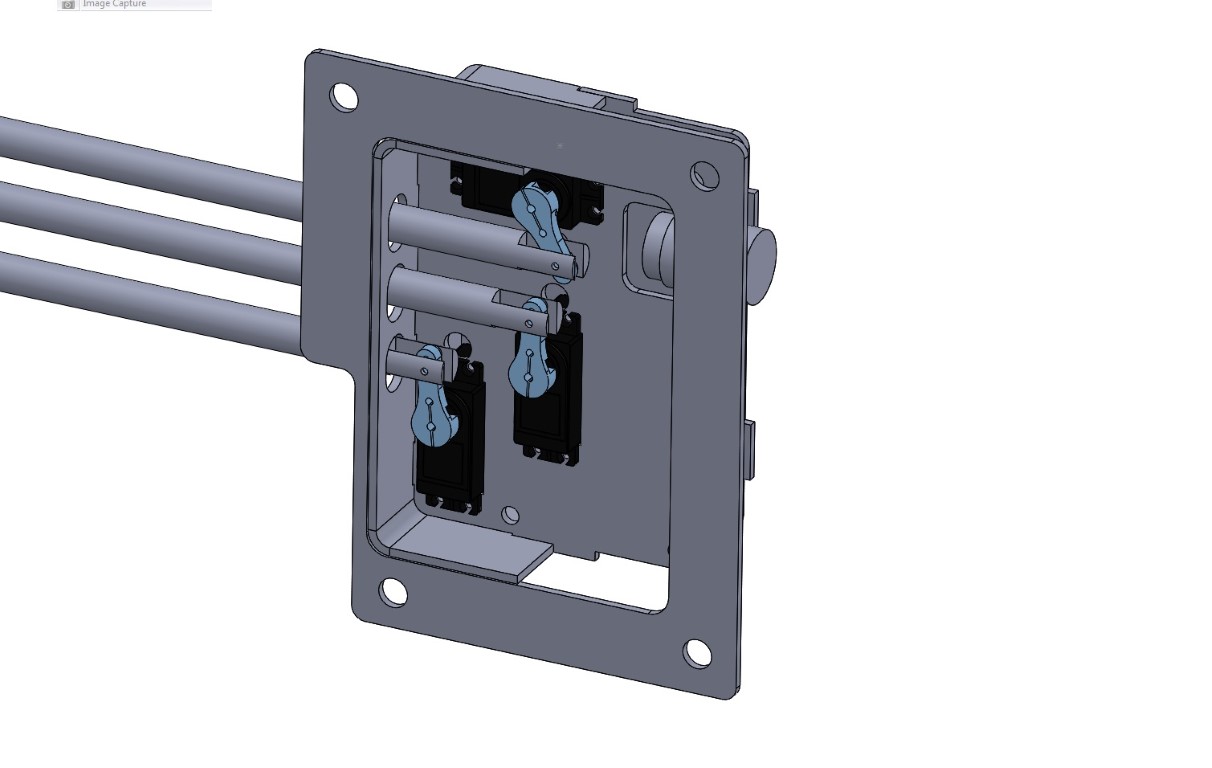
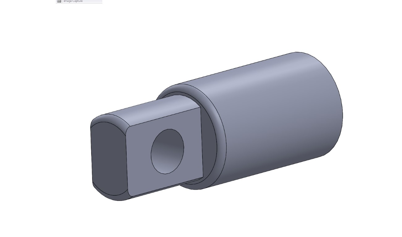
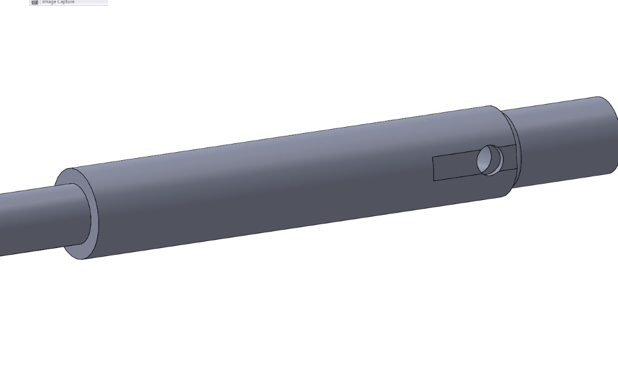
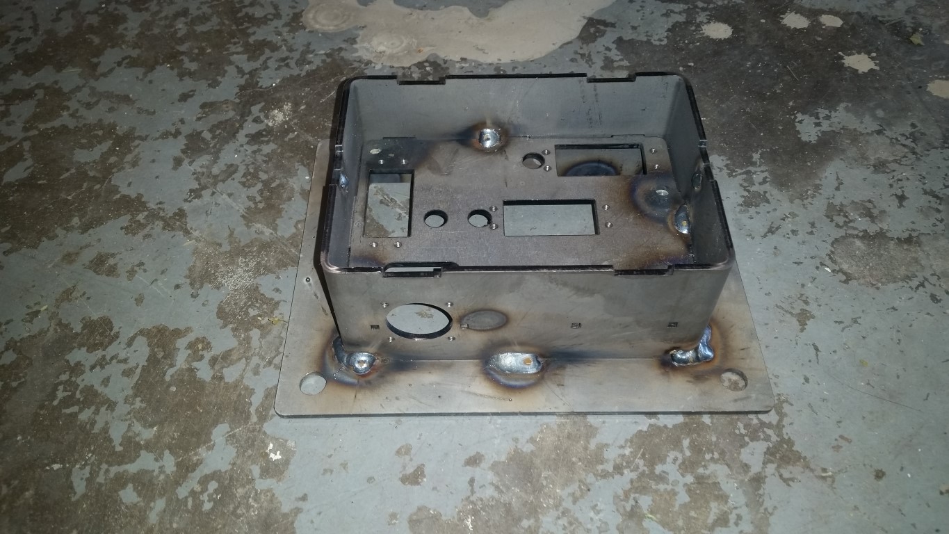
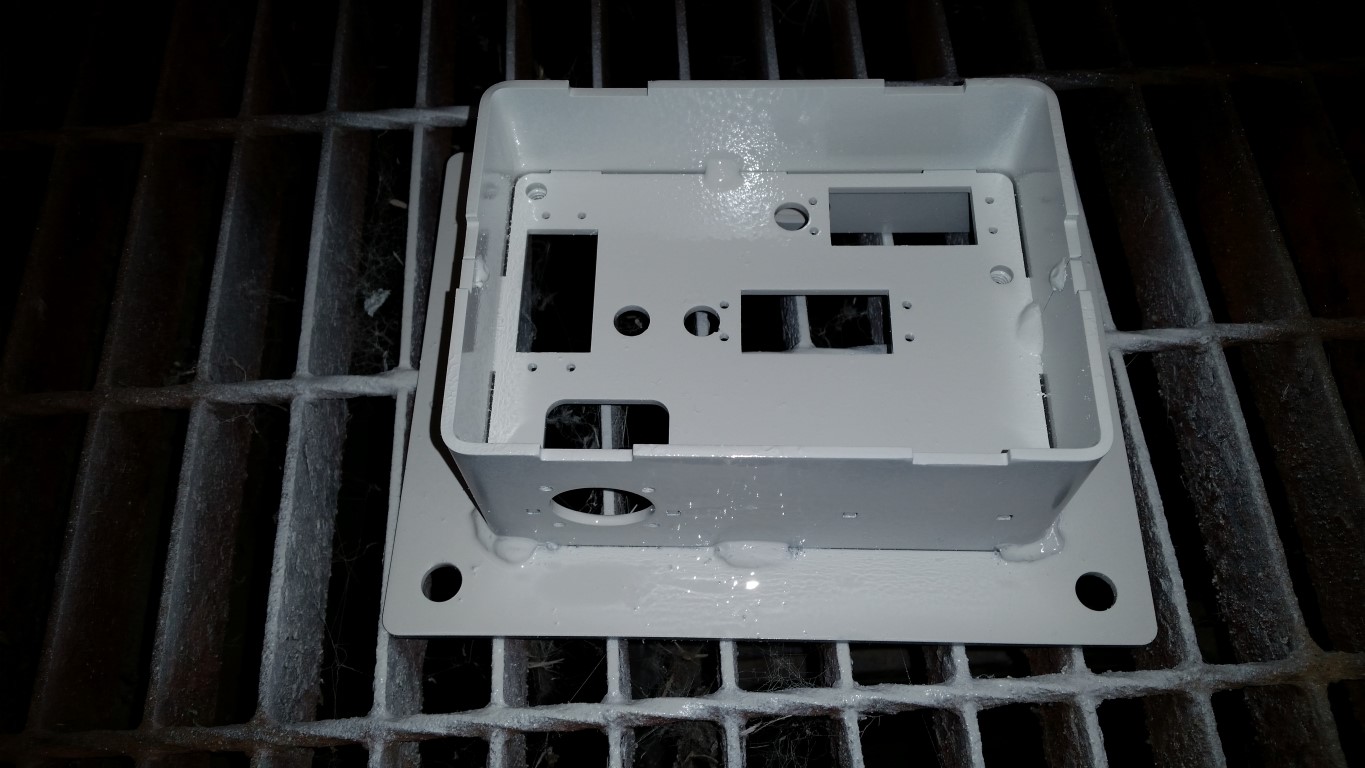
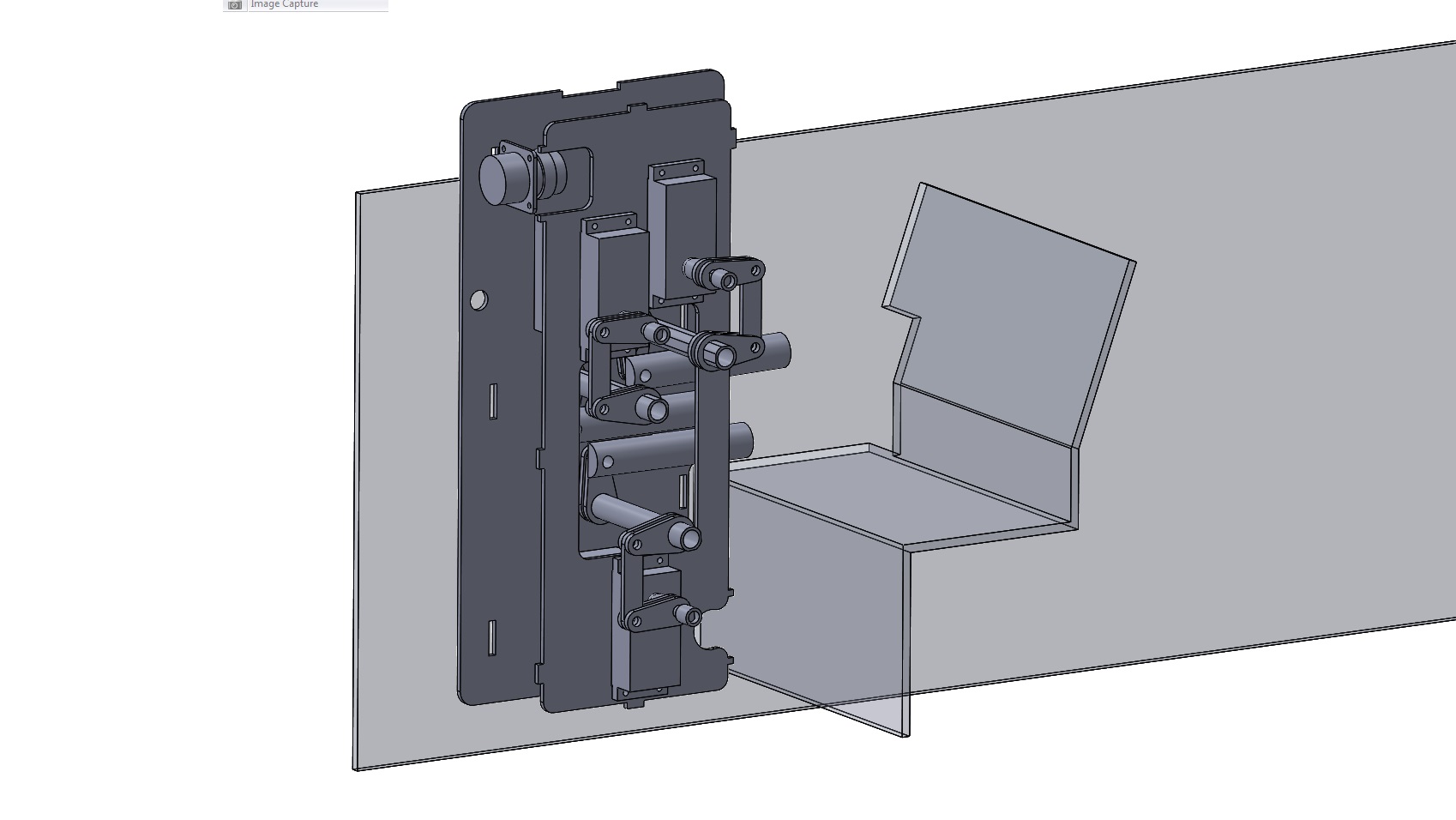
So late one night I came up with the (hopefully) brainwave of using my existing control valves, but adding digital control to them using radio control servo valves. This is the second version of the servo box for the arm functions:
20141220_005.jpg

20141220_006.jpg%20width=400

20141220_007.jpg

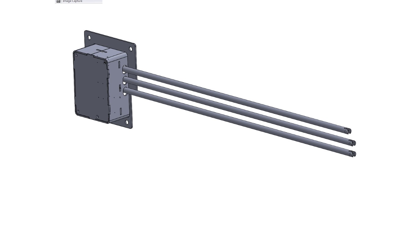
For those interested, the idea is to use a RC servo control board, coupled to PSP style thumb sticks and RC high torque servos to manipulate the aux and motor mechanical actuators.
The RC servo control board is this one:
0J2336.1200.jpg


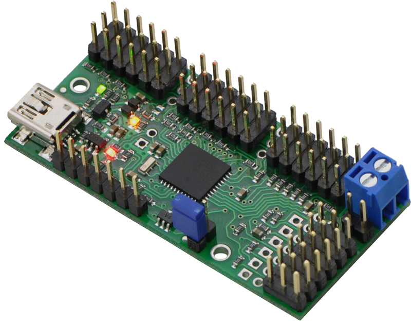
(From the Pololu.com website)
Basically, this little thing outputs a RC servo command based on either direct computer input, or some manipulated electronic input.
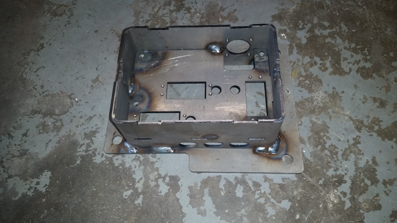
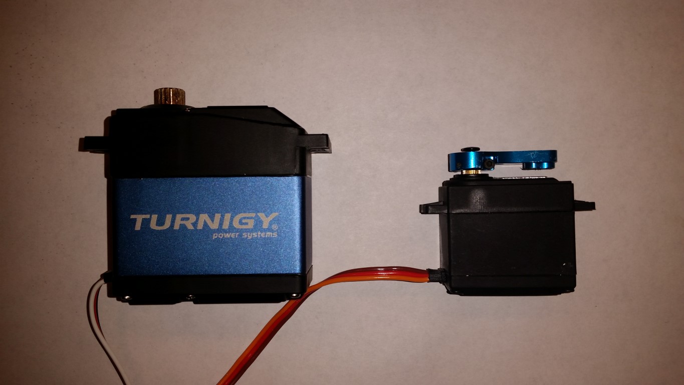
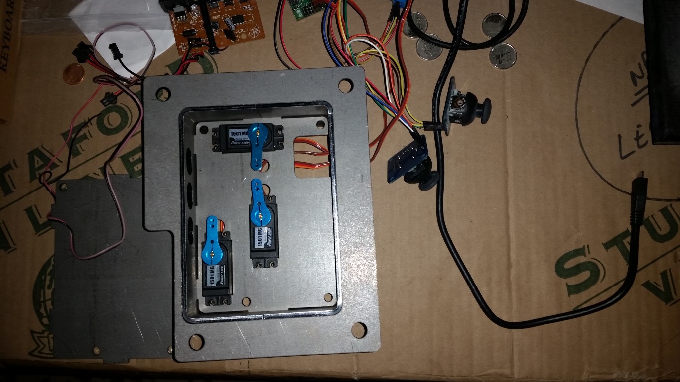
So here are the steel parts as received from the laser, plus test fitting the servos:
20141220_001.jpg

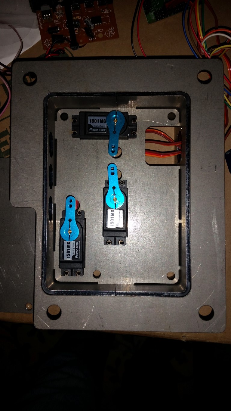
This photo includes the thumb controllers:
20141220_002.jpg

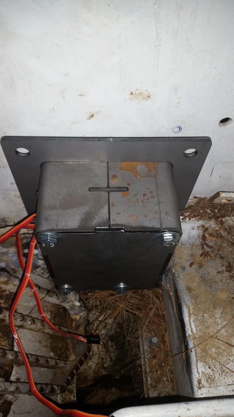
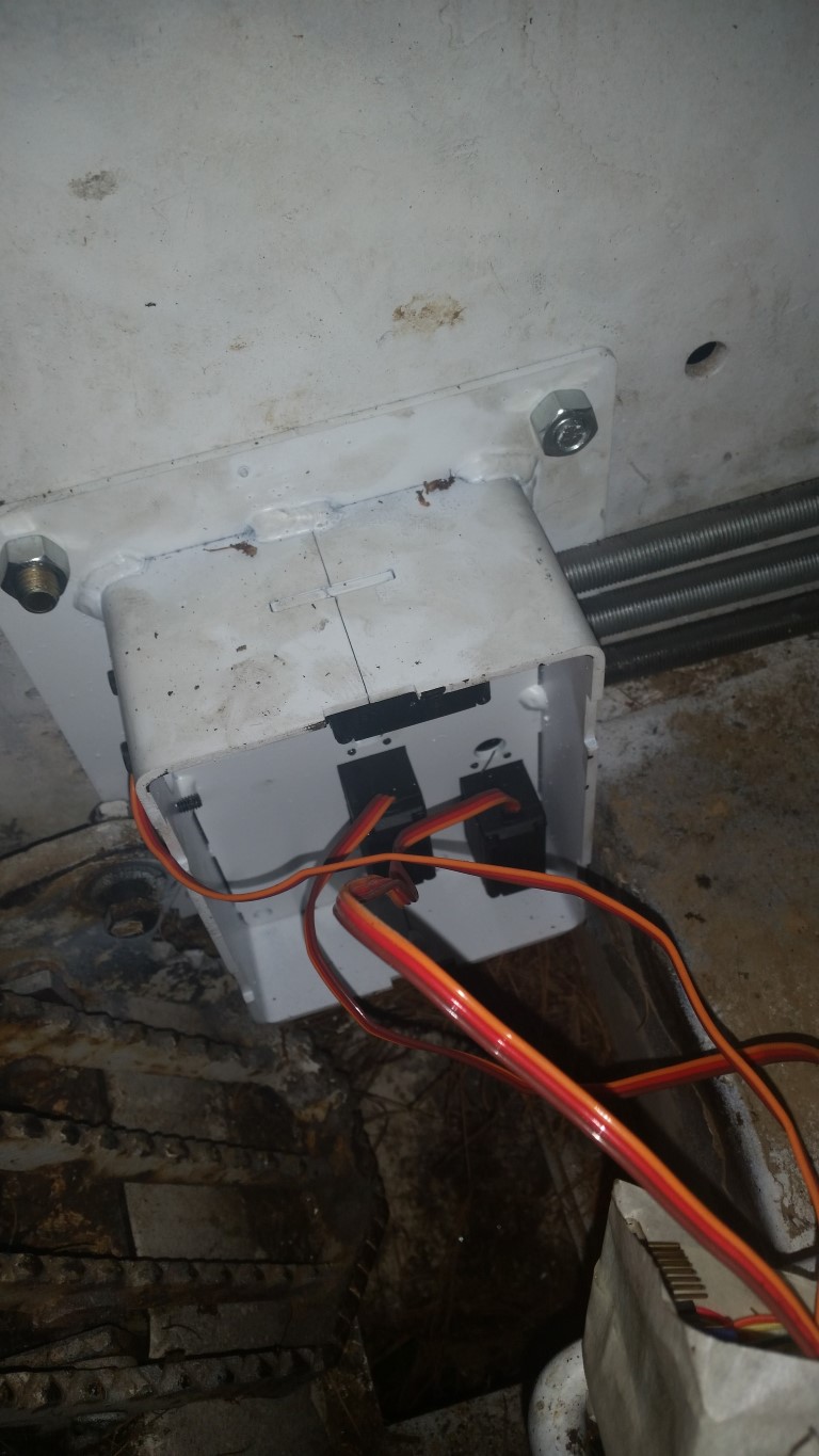
Ok, so I dawdled off to the office to TIG in the various nuts and tap the various holes:
20141220_003.jpg

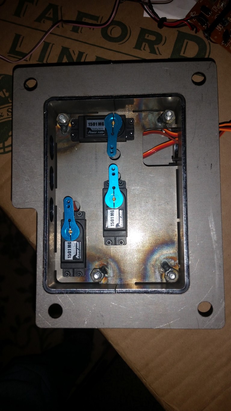
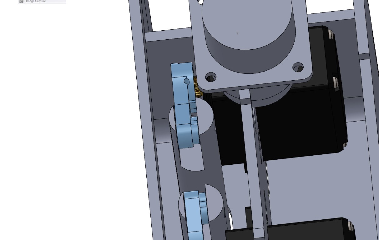
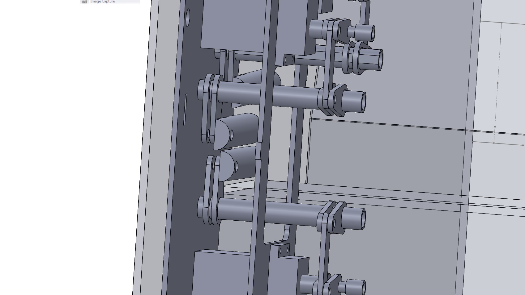
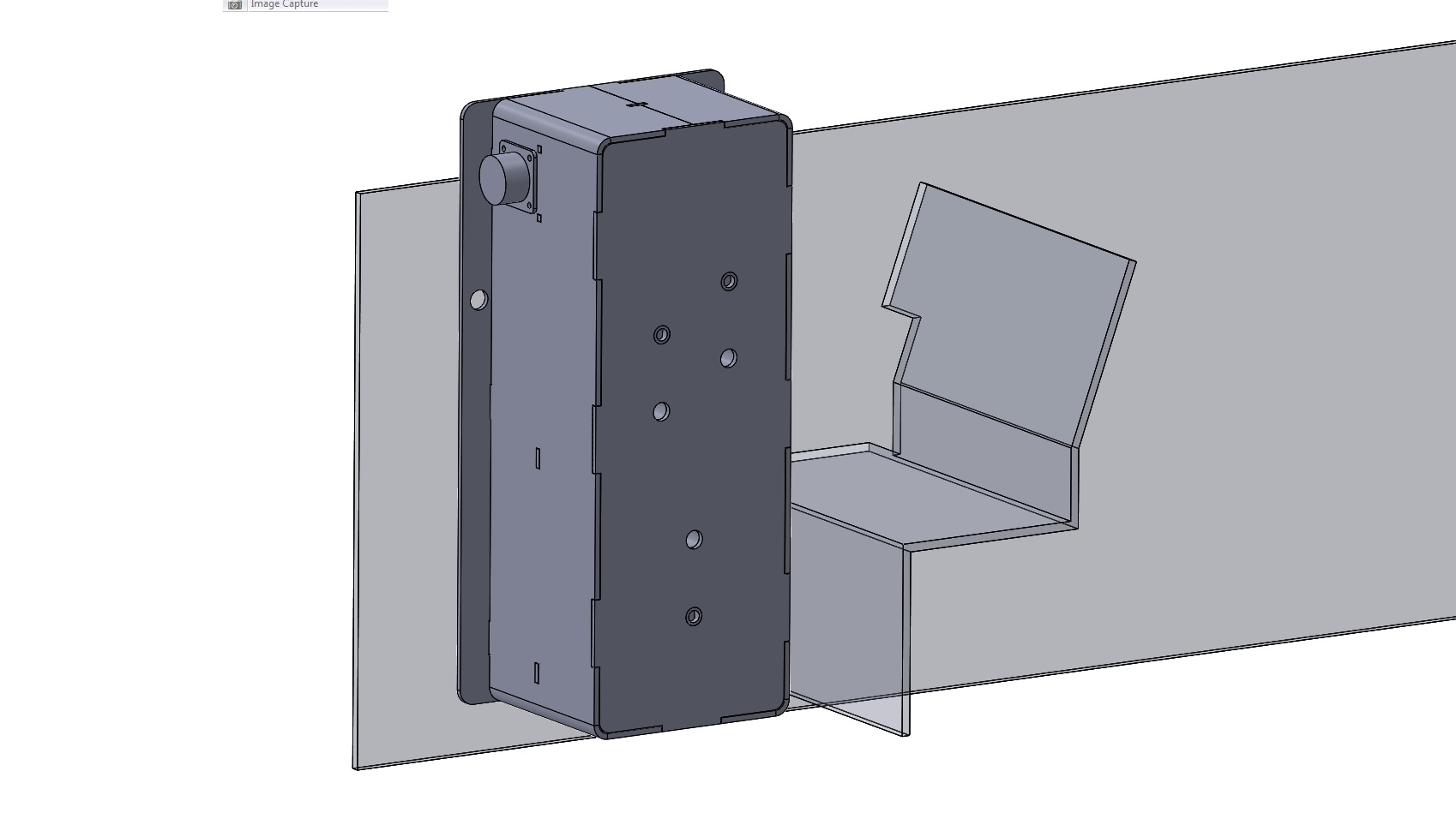
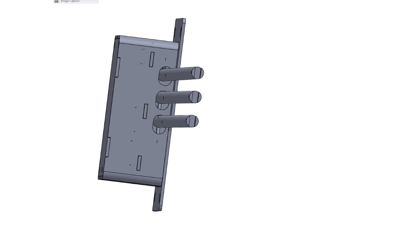
I spent a lot of time finding models for the servos to plonk into my box model. Unfortunately for me, I spent less time on the servo arm models and thought that my approximation of their size would do.
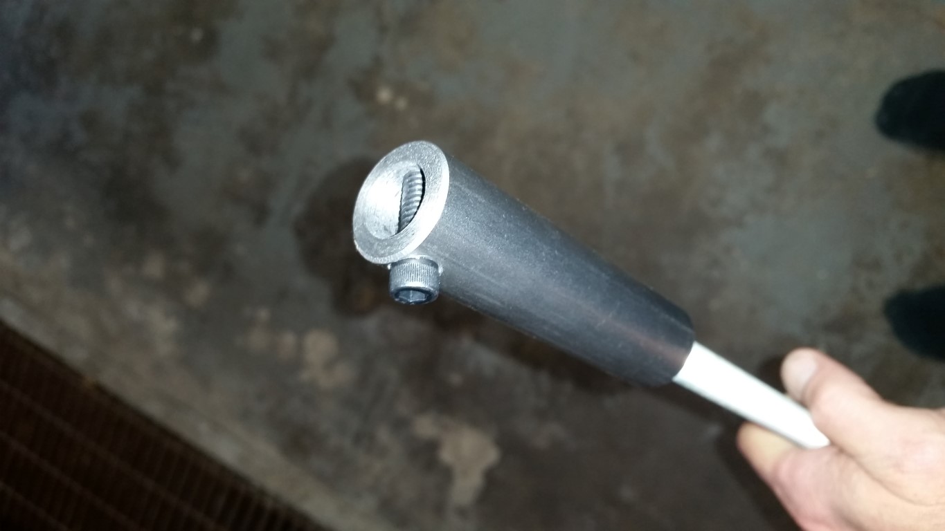
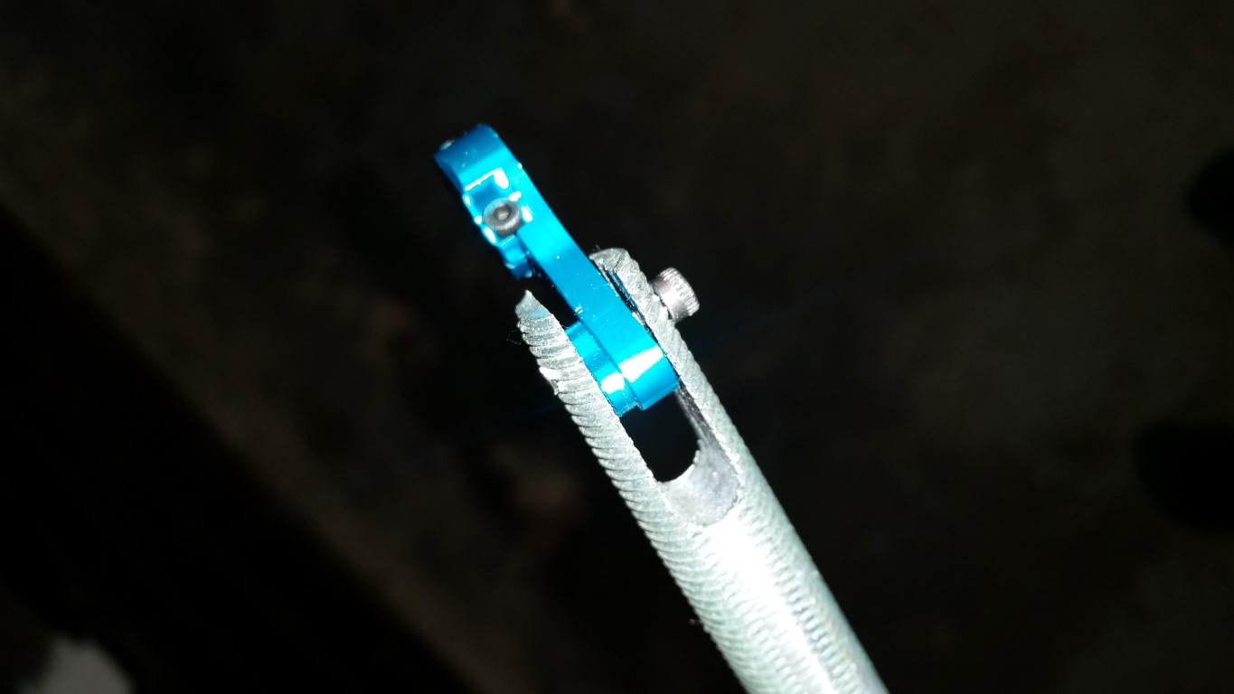
Assumption is the mother of all f ups, so this is the result of the assumption:
20141220_004.jpg

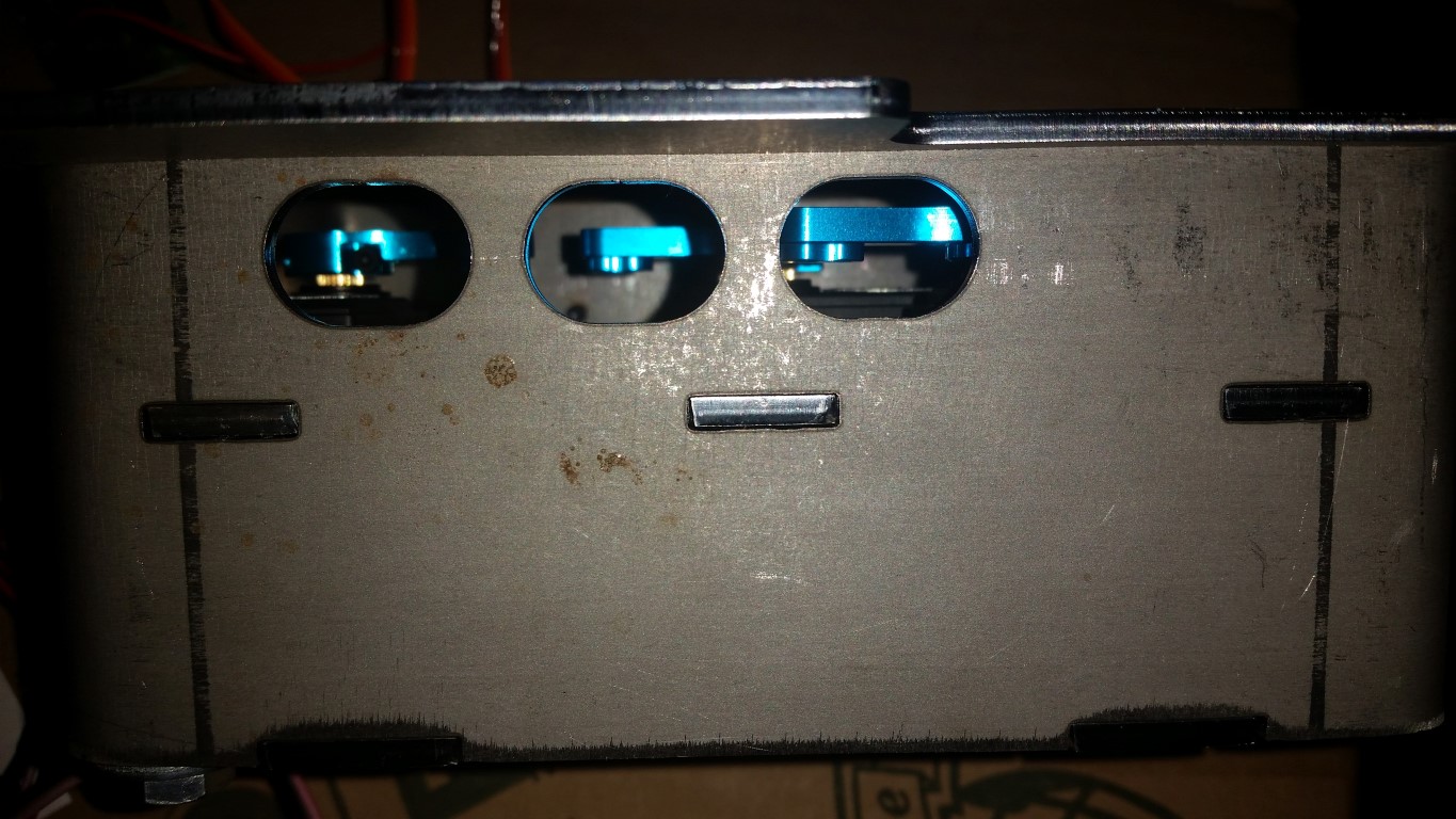
I have a couple of options to get the push/pull rods to be centered in the slots, but it is not looking good for a generic solution.
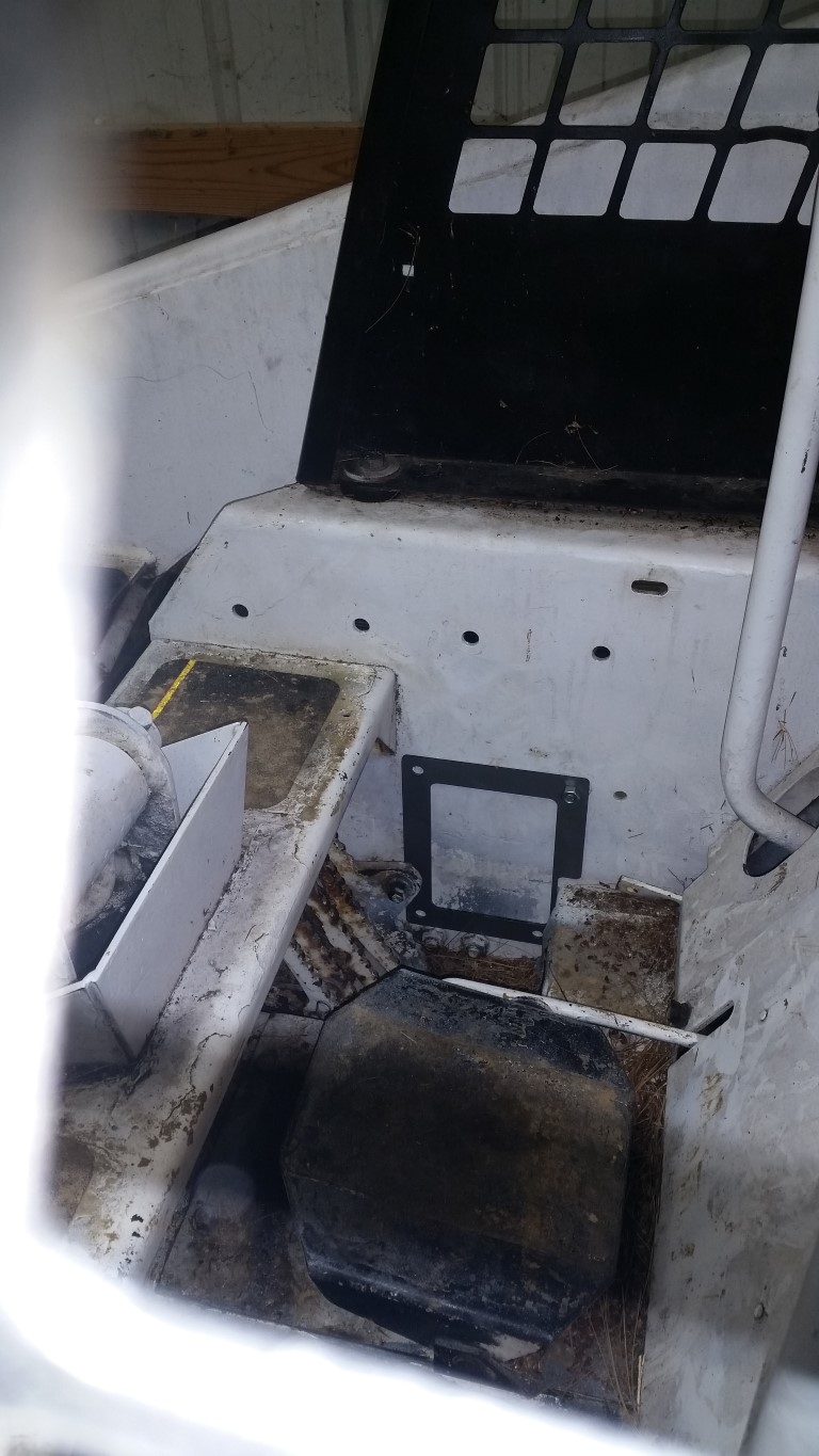
In my defense, this whole thing is designed to be able to fit into the space of the manual control arms and require zero modifications the little machine, except drilling of some holes.
Don't expect regular updates on this post. This is going to require quite a lot of experimentation and trial and error, but the purpose of posting was to encourage my progress,
 

discountufoparts

Well-known member
Joined
Sep 7, 2011
Messages
111
I think a lot of people would be interested in this. I would be myself not so much for one of my machine's internals as for the idea of a control system for a firewood processor I am building to go on the front of my Bobcat. Also I own a 630 and have been completely through it so if you have any questions with the hydraulics I know that machine fairly well.
 

Tazza

Moderator
Staff member
Joined
Dec 7, 2004
Messages
16,834
I think a lot of people would be interested in this. I would be myself not so much for one of my machine's internals as for the idea of a control system for a firewood processor I am building to go on the front of my Bobcat. Also I own a 630 and have been completely through it so if you have any questions with the hydraulics I know that machine fairly well.
This is very cool, reminds me of another forum i'm on that we have modified manual projectile casting machines to run automatically.
I expect to see updates on this :) Be it good or bad things you have found out.
How are you going to work the centering part out? so the servo always returns to a set point?
 
OP
OP
P

peebeeaitch

Well-known member
Joined
Dec 3, 2012
Messages
115
This is very cool, reminds me of another forum i'm on that we have modified manual projectile casting machines to run automatically.
I expect to see updates on this :) Be it good or bad things you have found out.
How are you going to work the centering part out? so the servo always returns to a set point?
Thanks discountufoparts. I have delved fairly deeply into my little machine - I wrote it up in my "Reclamation" post. If it wasn't for this list I'd have torched the machine.
I have very high expectations of success with this project. The parts are cheap, reliable, available and with a little fiddling can be adapted to the kind of thing you're thinking of.
 
OP
OP
P

peebeeaitch

Well-known member
Joined
Dec 3, 2012
Messages
115
Thanks discountufoparts. I have delved fairly deeply into my little machine - I wrote it up in my "Reclamation" post. If it wasn't for this list I'd have torched the machine.
I have very high expectations of success with this project. The parts are cheap, reliable, available and with a little fiddling can be adapted to the kind of thing you're thinking of.
Ok Tazza, I'm going to be motivated to completion for you :)
Perhaps I should delve a little into RC servo operation and what I'm trying to do as there seems to be more than cursory interest in this post. This is my understanding and if I'm wrong let me know. Also, for those who know this, please ignore.
RC servos operate on a signal sent to them by Pulse Width Modulation (PWM). 50 times per second the controller (either a RC receiver, or, in my case, a microprocessor board) sends a "On" signal to the servo. The amount of time that the "On" signal is present indicates to the servo to which position it should move. So, if the controller sends an "On" signal for 1.5 milliseconds (ms) the servo will move to the "neutral" position. A 1.0ms signal moves the servo to the "minimum" position and 2.0ms signals move it to the "max" position. The servos I am using have a 90deg swing, so 1.5ms moves it to 0deg, 1.0ms to -45deg and 2.0ms to +45deg. The "On" signal has to be followed by an "Off" signal, else the servo will just stay at +45deg.
This is pretty useful for RC devices - one would hate to have to recalibrate a model helicopter every time the power is cycled on one. The servo knows where 0deg is and when commanded to 0deg will return there.
The controller I am using is made for amateur robotics. It has 24 points at which you can connect stuff - either inputs to the device or outputs to the world. I reckon I will use most of them in this project:
Inputs
  1. Arm up/down
  2. Bucket close/open
  3. Aux one way/other way
  4. Left wheels fwd/rev
  5. Right wheels fwd/rev
  6. Engine starting or lap bar down
  7. Warning flasher on
  8. Oil pressure low
  9. Oil temperature high
  10. Fuel level
Outputs
  1. Servo 1
  2. Servo 2
  3. Servo 3
  4. Servo 4
  5. Servo 5
  6. Flasher
  7. Buzzer
  8. Fuel gauge
  9. Pressure gauge
  10. Temperature gauge
That's 20, but I'm sure I'll use up the rest of the 4 inputs/outputs (IO).
I bought the PSP style joysticks from AdaFruit:
http://www.adafruit.com/products/51...YQirK34bm1070IMoJsz_KP6ro4pVt0PtBshoCqBzw_wcB
One thing that I've noticed is that the response from the joystick, controller, servo is very non-linear. I press the joystick forward 5deg, nothing, then between 6 and 30deg the motion is pretty linear, then from 30deg to 60deg it is maxxed out. I can correct for the controller non-linearity in software, but if the joystick is mechanically not great there is precious little I can do about it.
More later.
 
OP
OP
P

peebeeaitch

Well-known member
Joined
Dec 3, 2012
Messages
115
Ok Tazza, I'm going to be motivated to completion for you :)
Perhaps I should delve a little into RC servo operation and what I'm trying to do as there seems to be more than cursory interest in this post. This is my understanding and if I'm wrong let me know. Also, for those who know this, please ignore.
RC servos operate on a signal sent to them by Pulse Width Modulation (PWM). 50 times per second the controller (either a RC receiver, or, in my case, a microprocessor board) sends a "On" signal to the servo. The amount of time that the "On" signal is present indicates to the servo to which position it should move. So, if the controller sends an "On" signal for 1.5 milliseconds (ms) the servo will move to the "neutral" position. A 1.0ms signal moves the servo to the "minimum" position and 2.0ms signals move it to the "max" position. The servos I am using have a 90deg swing, so 1.5ms moves it to 0deg, 1.0ms to -45deg and 2.0ms to +45deg. The "On" signal has to be followed by an "Off" signal, else the servo will just stay at +45deg.
This is pretty useful for RC devices - one would hate to have to recalibrate a model helicopter every time the power is cycled on one. The servo knows where 0deg is and when commanded to 0deg will return there.
The controller I am using is made for amateur robotics. It has 24 points at which you can connect stuff - either inputs to the device or outputs to the world. I reckon I will use most of them in this project:
Inputs

Arm up/down
Bucket close/open
Aux one way/other way
Left wheels fwd/rev
Right wheels fwd/rev
Engine starting or lap bar down
Warning flasher on
Oil pressure low
Oil temperature high
Fuel level

Outputs

Servo 1
Servo 2
Servo 3
Servo 4
Servo 5
Flasher
Buzzer
Fuel gauge
Pressure gauge
Temperature gauge

That's 20, but I'm sure I'll use up the rest of the 4 inputs/outputs (IO).
I bought the PSP style joysticks from AdaFruit:
http://www.adafruit.com/products/512?gclid=CjwKEAiA_NmkBRCe3ubC1aWAtEcSJACxkkbqkqgxmQBYQirK34bm1070IMoJsz_KP6ro4pVt0PtBshoCqBzw_wcB
One thing that I've noticed is that the response from the joystick, controller, servo is very non-linear. I press the joystick forward 5deg, nothing, then between 6 and 30deg the motion is pretty linear, then from 30deg to 60deg it is maxxed out. I can correct for the controller non-linearity in software, but if the joystick is mechanically not great there is precious little I can do about it.
More later.
WARNING: THIS IS PRETTY SHOCKING (REALLY)
Ok, so this morning I wanted to work on the links from the servo box to the control block. I needed to measure to hole through the shaft so picked up the plastic digital caliper I had bought from that super el-cheapo tools shop that has a nautical theme in its name.
Luckily I've got a bit of feeling for dimensions so when I measured the hole diameter and it came back as 246.3mm I knew there was something wrong. Zero'ed the caliper and again I measured, this time the diameter was -16.1mm, which in itself was interesting. No matter what I did I could not get a repeatable reading. This is the setup:
20141226_131251.jpg

In the middle centre one can see the little hole I was trying to measure. To get there I needed to maneuver the caliper in and down past the leadlight. Same on the way out to get the reading.
After a lot of screwing around trying to figure out what was going on I had a brainwave and moved the leadlight some distance away. Suddenly all readings were repeatable!
So this is the WARNING: BE CAREFUL WHEN USING CHEAP CALIPERS NEAR MAINS FREQUENCY, the mains may actually change the reading. Unbelievable. Note: I then went and got my expensive Mitutoyo it did not suffer from this insanity. Imagine wanting a little light to check a reading and the reading changes! And also, my bigger el-cheapo stainless caliper suffers from random zeroing of the origin depending on the speed one opens and closes the jaws.
So, I am now going to purchase two Mitutoyo's to complement the one I have.
 
OP
OP
P

peebeeaitch

Well-known member
Joined
Dec 3, 2012
Messages
115
WARNING: THIS IS PRETTY SHOCKING (REALLY)
Ok, so this morning I wanted to work on the links from the servo box to the control block. I needed to measure to hole through the shaft so picked up the plastic digital caliper I had bought from that super el-cheapo tools shop that has a nautical theme in its name.
Luckily I've got a bit of feeling for dimensions so when I measured the hole diameter and it came back as 246.3mm I knew there was something wrong. Zero'ed the caliper and again I measured, this time the diameter was -16.1mm, which in itself was interesting. No matter what I did I could not get a repeatable reading. This is the setup:

In the middle centre one can see the little hole I was trying to measure. To get there I needed to maneuver the caliper in and down past the leadlight. Same on the way out to get the reading.
After a lot of screwing around trying to figure out what was going on I had a brainwave and moved the leadlight some distance away. Suddenly all readings were repeatable!
So this is the WARNING: BE CAREFUL WHEN USING CHEAP CALIPERS NEAR MAINS FREQUENCY, the mains may actually change the reading. Unbelievable. Note: I then went and got my expensive Mitutoyo it did not suffer from this insanity. Imagine wanting a little light to check a reading and the reading changes! And also, my bigger el-cheapo stainless caliper suffers from random zeroing of the origin depending on the speed one opens and closes the jaws.
So, I am now going to purchase two Mitutoyo's to complement the one I have.
A little bit of planning today.
There are many, many posts on this site that speak of the challenging pleasures of getting to the control block on older machines. Most of them speak of the challenge, few of the lacerated fingers from worn hoses. Anyway, this is the end of the control block to which the servo pusher must join:
20141226_131246.jpg

(This is deep, deep inside the machine - Wolverine or Edward Scissorhands spring to mind - the red stuff on the accelerator cable is blood from my fingers). Notice the ropes pulling the hoses to one side so that I could get in there.
I put some more effort into modeling up the servo arms (with a Mitutoyo):
20141226200001.jpg

20141226200002.jpg

The grated fingers were endured in order to measure the end of the control block spindle, modelled below:
20141226200003.jpg

Here's the end of the push rod. It's threaded from the left which allows fine'ish adjustment of the total length of the push rod (the final adjustment is done with software in the controller):
20141226200004.jpg

This is a dry fit of the servo box:
20141226_131302.jpg

(Excuse the pine needles, a result of the Prestolite starter and the Briggs and Stratton repower, and a close, self induced incendiary event).
More later.
 
OP
OP
P

peebeeaitch

Well-known member
Joined
Dec 3, 2012
Messages
115
A little bit of planning today.
There are many, many posts on this site that speak of the challenging pleasures of getting to the control block on older machines. Most of them speak of the challenge, few of the lacerated fingers from worn hoses. Anyway, this is the end of the control block to which the servo pusher must join:

(This is deep, deep inside the machine - Wolverine or Edward Scissorhands spring to mind - the red stuff on the accelerator cable is blood from my fingers). Notice the ropes pulling the hoses to one side so that I could get in there.
I put some more effort into modeling up the servo arms (with a Mitutoyo):


The grated fingers were endured in order to measure the end of the control block spindle, modelled below:

Here's the end of the push rod. It's threaded from the left which allows fine'ish adjustment of the total length of the push rod (the final adjustment is done with software in the controller):

This is a dry fit of the servo box:

(Excuse the pine needles, a result of the Prestolite starter and the Briggs and Stratton repower, and a close, self induced incendiary event).
More later.
Rightey.
Started on the pusher rods. The tube is 100mm long, threaded about 55mm long, the relief drilled for the remaining 45mm. The thread is 1/2"-20, which should give me pretty fine zeroing adjustment. The capscrew that goes through the spool hole is 6.35mm (1/4") from the end of the push. This is the end that attaches to the control block spool.
20141229_140934.jpg

The other end is a problem (where it attaches to the servo). To explain the logic a little, there is a slot in the pump front vertical cover panel through which the right pedal push rod passes. I didn't want to permanently modify the little machine so I designed this whole contraption to use this slot (all three rods). That required designing the servo box so that the rods would be as close as possible to the right side of the main chassis. This meant that the servo horns could only be a certain height, and I was sure I would be able to find steel horns to which I could weld some robust disk with a decent size attachment bolt. This, sadly, is not to be found. So, for the interim I decided to use what I could get.
20141229_112949.jpg

(The slot is visible on the right with the OEM push "bar" just sticking out).
I give this solution of mine a RR (Robustness Rating) equal to the chances of teenagers not having hormonal mood swings - very low. It's actually rather serious as I'm now thinking that I may have to totally redesign the servo box. Plus, the servo box fits in nicely in the gap between the pump vertical wall and the foot pedal. If I change the box I'm going to have to cut the foot pedals out (because the bolts are totally rusted in), or go for some complicated bell-crank system. This is becoming a bit of a bother.
Here's the servo end:
20141229_140941.jpg

And I've learnt that if I don't do this properly, the machine is going to fail in the middle of the driveway in the middle of a blizzard. In fact, I've just decided to try this box out and immediately design the replacement. Damn.
Anyway, here is the welding on the box:
20141229_120834.jpg

20141229_120842.jpg

And some paint:
20141229_135222.jpg
 

Tazza

Moderator
Staff member
Joined
Dec 7, 2004
Messages
16,834
Rightey.
Started on the pusher rods. The tube is 100mm long, threaded about 55mm long, the relief drilled for the remaining 45mm. The thread is 1/2"-20, which should give me pretty fine zeroing adjustment. The capscrew that goes through the spool hole is 6.35mm (1/4") from the end of the push. This is the end that attaches to the control block spool.

The other end is a problem (where it attaches to the servo). To explain the logic a little, there is a slot in the pump front vertical cover panel through which the right pedal push rod passes. I didn't want to permanently modify the little machine so I designed this whole contraption to use this slot (all three rods). That required designing the servo box so that the rods would be as close as possible to the right side of the main chassis. This meant that the servo horns could only be a certain height, and I was sure I would be able to find steel horns to which I could weld some robust disk with a decent size attachment bolt. This, sadly, is not to be found. So, for the interim I decided to use what I could get.

(The slot is visible on the right with the OEM push "bar" just sticking out).
I give this solution of mine a RR (Robustness Rating) equal to the chances of teenagers not having hormonal mood swings - very low. It's actually rather serious as I'm now thinking that I may have to totally redesign the servo box. Plus, the servo box fits in nicely in the gap between the pump vertical wall and the foot pedal. If I change the box I'm going to have to cut the foot pedals out (because the bolts are totally rusted in), or go for some complicated bell-crank system. This is becoming a bit of a bother.
Here's the servo end:

And I've learnt that if I don't do this properly, the machine is going to fail in the middle of the driveway in the middle of a blizzard. In fact, I've just decided to try this box out and immediately design the replacement. Damn.
Anyway, here is the welding on the box:


And some paint:
Awesome progress.
Yeah, the hoses when they wear through the rubber are really nasty on your hands, i have been cut pretty badly a few times from them, it's a good idea to cover the exposed parts with insulation tape to try and protect your paws as they dig around.
 
OP
OP
P

peebeeaitch

Well-known member
Joined
Dec 3, 2012
Messages
115
Awesome progress.
Yeah, the hoses when they wear through the rubber are really nasty on your hands, i have been cut pretty badly a few times from them, it's a good idea to cover the exposed parts with insulation tape to try and protect your paws as they dig around.
Thanks Tazza - read on for the two steps forward 5 back...
So I got busy yesterday getting the stuff in.
Here is progress:
20141231_01.jpg

This was after blood transfusion 4 from lacerated fingers, forearms, knuckles, etc. What's really predictable is that the hose with the rope on it, in the most prominent position for this job, is the frayed one. So, every time I dipped my arm into the gap to attach, adjust, pick up a dropped something, whatever, I closed my eyes and prayed, and was rewarded with a slash.
Here is the other side:
20141231_02.jpg

Looks cool.
EPIC FAIL
Fail 1: When installing the story, I accidentally moved the bottom servo (driving the aux spool). This managed to strip the horn on the servo. I was infuriated, but soldiered on because I knew that version 2 is in the pipeline and so I wanted to confirm that everything else worked.
Fail 2: Adjusted up everything. I also managed to get, in addition to the grated fingers, carpal tunnel syndrome from adjusting the bushes in micro turns in order to keep the fingers away from the grater hose. Pushed the electronic joystick and following the tiniest motion, absolutely nothing. The servos aren't strong enough. They're fine for moving the spools once the detent is overcome, but not to overcome the detent. When I measured the force needed I forgot this little detail (oops).
I considered removing the detents from the spools, but that was really not the aim of the project.
Ok, so what now.
Today I redesigned the thing:
20150101_01.jpg

20150101_02.jpg

20150101_03.jpg

The new servos output 30 kg cm up from the previous failed 15 kg cm. I'm waiting for them now, plus all sorts of other stuff to make this work.
I will not be reinstalling the foot pedal controls anytime soon though - unless it snows. The pain is a serious deterrent.
 

discountufoparts

Well-known member
Joined
Sep 7, 2011
Messages
111
Thanks Tazza - read on for the two steps forward 5 back...
So I got busy yesterday getting the stuff in.
Here is progress:

This was after blood transfusion 4 from lacerated fingers, forearms, knuckles, etc. What's really predictable is that the hose with the rope on it, in the most prominent position for this job, is the frayed one. So, every time I dipped my arm into the gap to attach, adjust, pick up a dropped something, whatever, I closed my eyes and prayed, and was rewarded with a slash.
Here is the other side:

Looks cool.
EPIC FAIL
Fail 1: When installing the story, I accidentally moved the bottom servo (driving the aux spool). This managed to strip the horn on the servo. I was infuriated, but soldiered on because I knew that version 2 is in the pipeline and so I wanted to confirm that everything else worked.
Fail 2: Adjusted up everything. I also managed to get, in addition to the grated fingers, carpal tunnel syndrome from adjusting the bushes in micro turns in order to keep the fingers away from the grater hose. Pushed the electronic joystick and following the tiniest motion, absolutely nothing. The servos aren't strong enough. They're fine for moving the spools once the detent is overcome, but not to overcome the detent. When I measured the force needed I forgot this little detail (oops).
I considered removing the detents from the spools, but that was really not the aim of the project.
Ok, so what now.
Today I redesigned the thing:


The new servos output 30 kg cm up from the previous failed 15 kg cm. I'm waiting for them now, plus all sorts of other stuff to make this work.
I will not be reinstalling the foot pedal controls anytime soon though - unless it snows. The pain is a serious deterrent.
All great successes usually require many epic failures to precede them. That hose you are having a problem with you should, if you can afford to, replace with a built in 90 fitting on the end hose. I replaced both on that side of my machine with them and that valve bank is easier to access now.
 
OP
OP
P

peebeeaitch

Well-known member
Joined
Dec 3, 2012
Messages
115
All great successes usually require many epic failures to precede them. That hose you are having a problem with you should, if you can afford to, replace with a built in 90 fitting on the end hose. I replaced both on that side of my machine with them and that valve bank is easier to access now.
Thanks for the excellent suggestion. I'm going to strip the relevant graters and head off to the shop immediately.
 

Tazza

Moderator
Staff member
Joined
Dec 7, 2004
Messages
16,834
Thanks for the excellent suggestion. I'm going to strip the relevant graters and head off to the shop immediately.
The upgrated servos is a good idea.
I don't see why you can't remove the detent balls once all setup. It is simply removing a cap and the balls, not hard to remove, installing is another issue all together.
Sadly i giggled at the comments of the grater hose.... I feel your pain, i really do been there so many times. The worst part is the face they are never clean, every slice pushes dirt into the fresh wound to get infected.
 
OP
OP
P

peebeeaitch

Well-known member
Joined
Dec 3, 2012
Messages
115
The upgrated servos is a good idea.
I don't see why you can't remove the detent balls once all setup. It is simply removing a cap and the balls, not hard to remove, installing is another issue all together.
Sadly i giggled at the comments of the grater hose.... I feel your pain, i really do been there so many times. The worst part is the face they are never clean, every slice pushes dirt into the fresh wound to get infected.
Hey DiscountUFOParts, check this:
20150105_01.jpg

My local hydraulics supplier had these add on 90's (female/male on the two ends of the 90). I now have tons of space there, and while I was at it I replaced the grater. I didn't realize how much hose length the 90's saved - I reckon I could have shortened the hoses by at least 100mm.
Thanks again.
 
OP
OP
P

peebeeaitch

Well-known member
Joined
Dec 3, 2012
Messages
115
Hey DiscountUFOParts, check this:

My local hydraulics supplier had these add on 90's (female/male on the two ends of the 90). I now have tons of space there, and while I was at it I replaced the grater. I didn't realize how much hose length the 90's saved - I reckon I could have shortened the hoses by at least 100mm.
Thanks again.
Thanks Tazza for the commiseration. I agree with the stuffing the gunk into the wound, and it's usually right on the working parts of the fingers so really painful.
Anyhow, the new servos arrived today. Here's a size comparison:
20150105_02.jpg

Now, some lasering.
So, today, the biggest storm of the winter is predicted to come through with tons of snow. That meant that I spent the day taking everything off that I had put on the machine for the servos and then restoring the foot pedal operation. As soon as the lasering is done, I need to take it all off again and put on my servo story back on. Luckily the hoses aren't going to be wounding me.
 
OP
OP
P

peebeeaitch

Well-known member
Joined
Dec 3, 2012
Messages
115
Thanks Tazza for the commiseration. I agree with the stuffing the gunk into the wound, and it's usually right on the working parts of the fingers so really painful.
Anyhow, the new servos arrived today. Here's a size comparison:

Now, some lasering.
So, today, the biggest storm of the winter is predicted to come through with tons of snow. That meant that I spent the day taking everything off that I had put on the machine for the servos and then restoring the foot pedal operation. As soon as the lasering is done, I need to take it all off again and put on my servo story back on. Luckily the hoses aren't going to be wounding me.
Forgot to say. I will in all likelihood remove the detents when this is all sorted out, but they're really useful at the moment providing a zero reference. If I remove them I have no way of adjusting the servos and linkages to neutral.
Let's see what this week brings.
 

Tazza

Moderator
Staff member
Joined
Dec 7, 2004
Messages
16,834
Forgot to say. I will in all likelihood remove the detents when this is all sorted out, but they're really useful at the moment providing a zero reference. If I remove them I have no way of adjusting the servos and linkages to neutral.
Let's see what this week brings.
The new servos look much better.
That is bad luck that you needed to change everything back so you could use the machine, better than using a shovel i guess....
 

discountufoparts

Well-known member
Joined
Sep 7, 2011
Messages
111
Hey DiscountUFOParts, check this:

My local hydraulics supplier had these add on 90's (female/male on the two ends of the 90). I now have tons of space there, and while I was at it I replaced the grater. I didn't realize how much hose length the 90's saved - I reckon I could have shortened the hoses by at least 100mm.
Thanks again.
That looks way easier to work on now.
 
Top