630 - Repower

Help Support SkidSteer Forum:

peebeeaitch

Well-known member
Joined
Dec 3, 2012
Messages
115
2014-09-06
So today I went out to try and start the little machine that had been "stored" under the tree for a couple of months because I could not get it to start, again. Again it did not start.
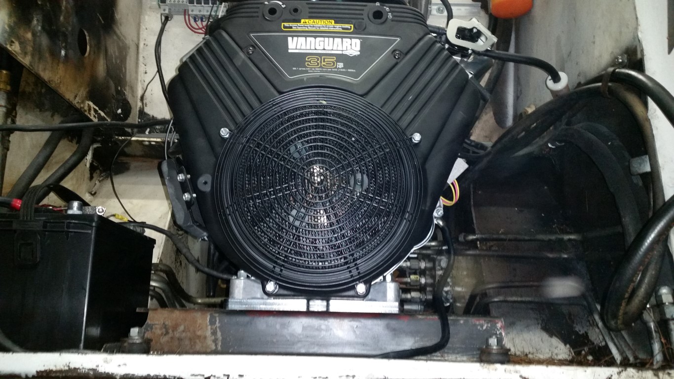
I decided to re-engine the machine.
I know that most opinion on this forum is to leave the motor stock and rebuild, but I really don't have the interest, skill, time, or frankly money to do this. I have read of rebuilds of the Wisconsin VH4D costing in the region of $2500, which seems extreme.
I originally considered a diesel from a reefer, and various other sources, but had the brain-wave of looking for some gas (petrol) powered job.
This turned out to be the snag. The Wisconsin outputs 28 HP and 66 ft-lbs of torque. Finding a 28 HP horizontal output shaft air cooled after market engine is easy, but luckily I thought of the torque. The 28 HP motors out there (usually V Twins) put out much less torque (like in the 40's or 50's). I read somewhere that the way one decides if one needs power or torque is to ask if it is measured in time - low time=more HP (kW), no time, but ability, means torque. Thinking about turning the pumps, it is not so much the speed of turning as the ability to turn them. So I started the search for a V Twin that could generate the required torque.
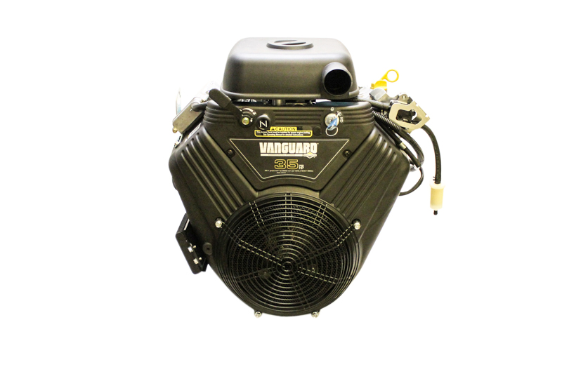
24.5 million websites later I found the Briggs and Stratton Vanguard 35 HP, horizontal output shaft, V Twin with 62 ft-lbs of torque. I am a metric person so ft-lbs means as much to me as banana-furlongs. But I reckoned that the 6 ft-lbs lost would be made up by the fact that the motor was 30 years newer.
I have had really bad experiences with B&S in my former home country and was very reluctant to buy one - perhaps the scrap is exported. I have had great experiences with Robin, though they do not make an engine of this size that I could find. A couple of websites later I was convinced to try the B&S as the Vanguard series is apparently made in Japan in the Daihatsu factory which is 40% owned by Toyota - all good.
I tried one site that had very low prices, but requesting help on selecting the one of 15 models of engine helped nothing.
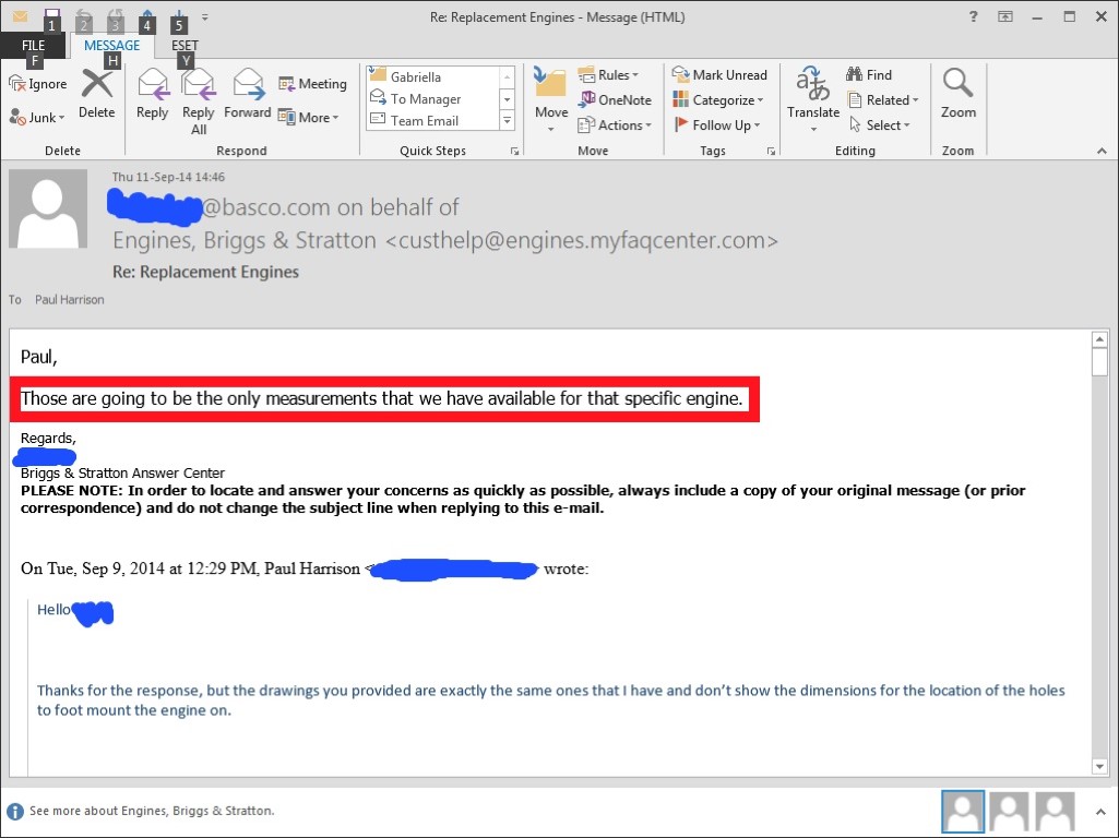
I contacted Briggs online help to ask what the engine codes meant but was told that it was a "parts list" thing. It appears B&S make 100000 different engines, all with some minor mod, that creates a new part number. Trying to find out what engine would work seemed almost insane.
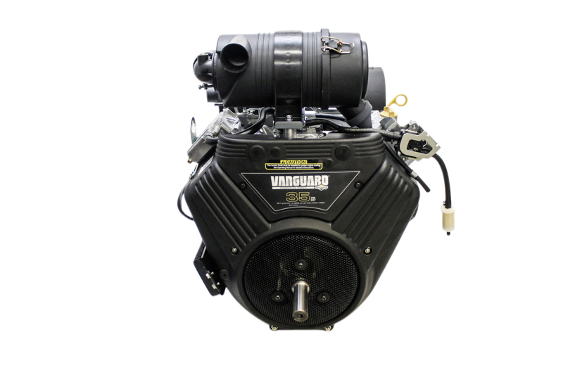
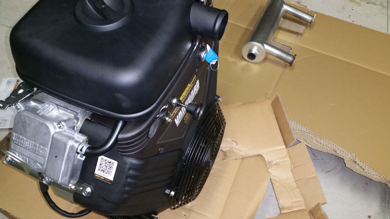
Another site popped up in my search (SmallEngineWarehouse) and which has absolutely incredible photos of the engines. This helped narrow down the options. Anyway, suffice it to say that 10 hours later I purchased a 613477-2141-G1. This has a key-switch, choke and throttle on the body.
Please also do not take the trouble to phone the company I purchased the motor from and ask anything about the motor, especially when you start the call with "I am trying to repower a Bobcat". Every question was answered with the standard "Well, I can't say if it will work or won't work because you are putting it into a machine for which it was not intended". Even questions like "Can I remove the choke on the cover and replace it with a cable" were met with the same liability exclusion.
They shipped the motor to me in two days (!!!) and when it arrived I was relieved to see the "Made in Japan" on the cardboard!
2014-09-08_05.jpg

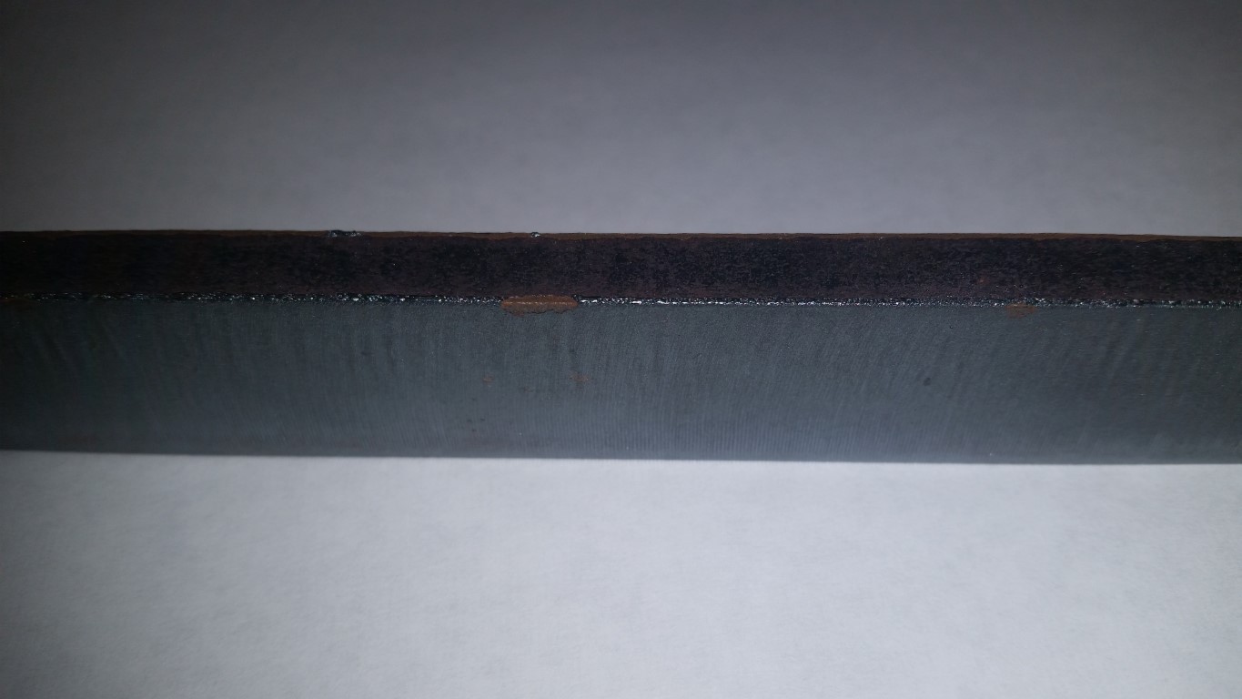
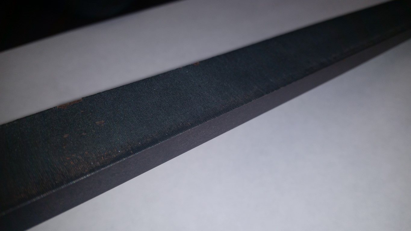
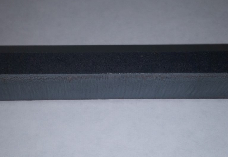
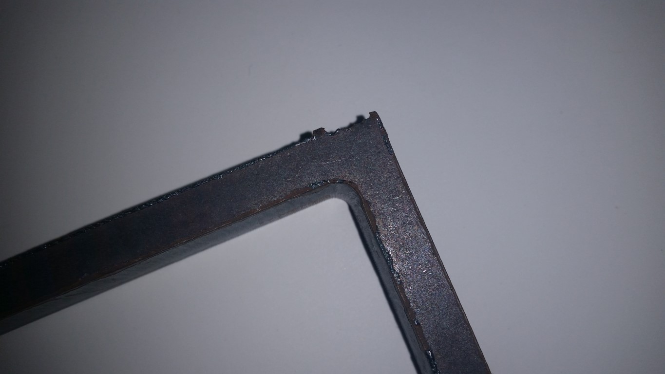
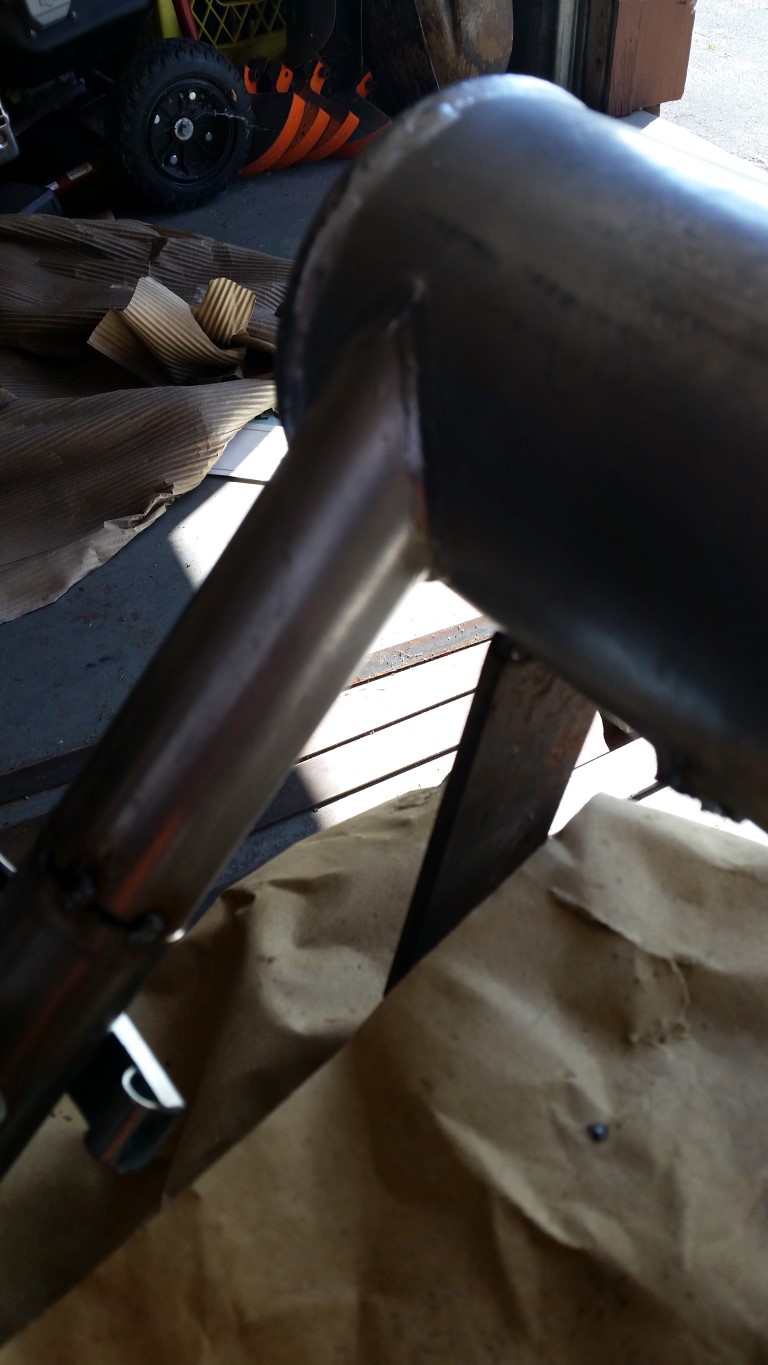
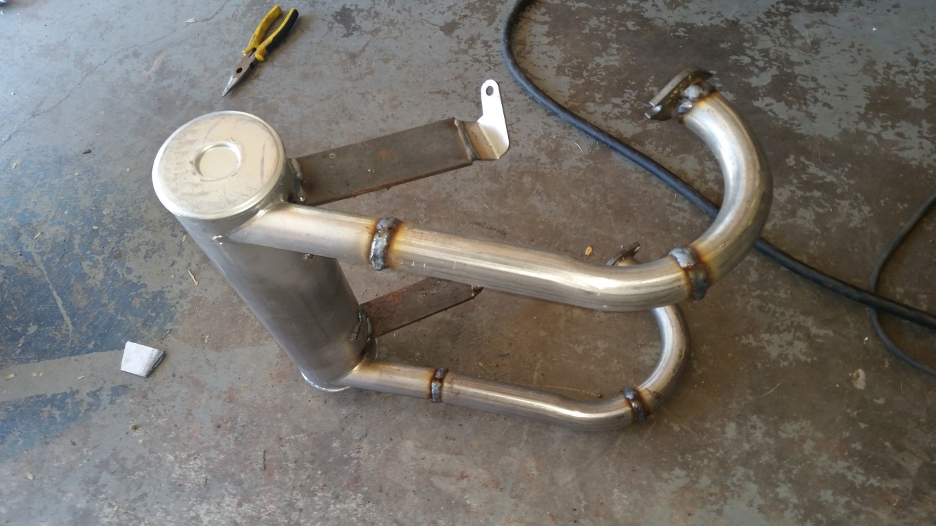
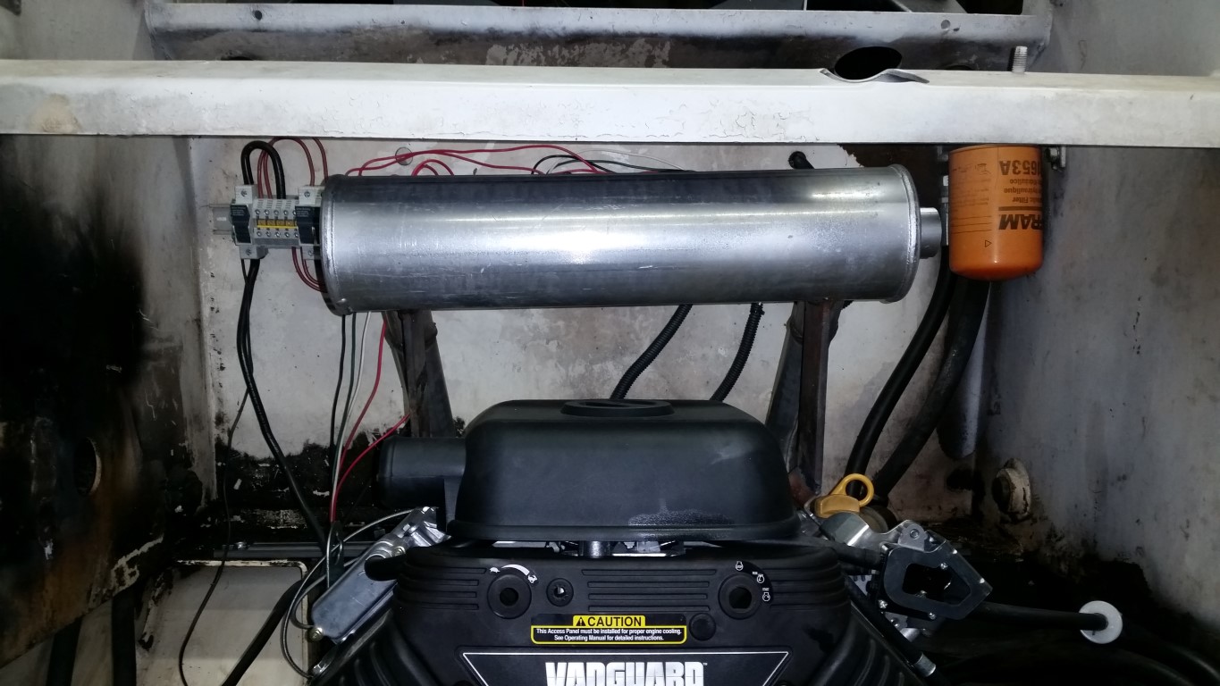
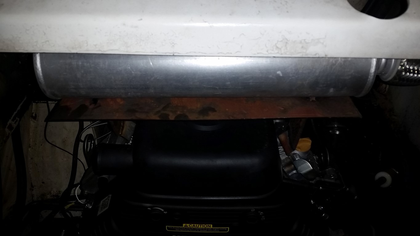
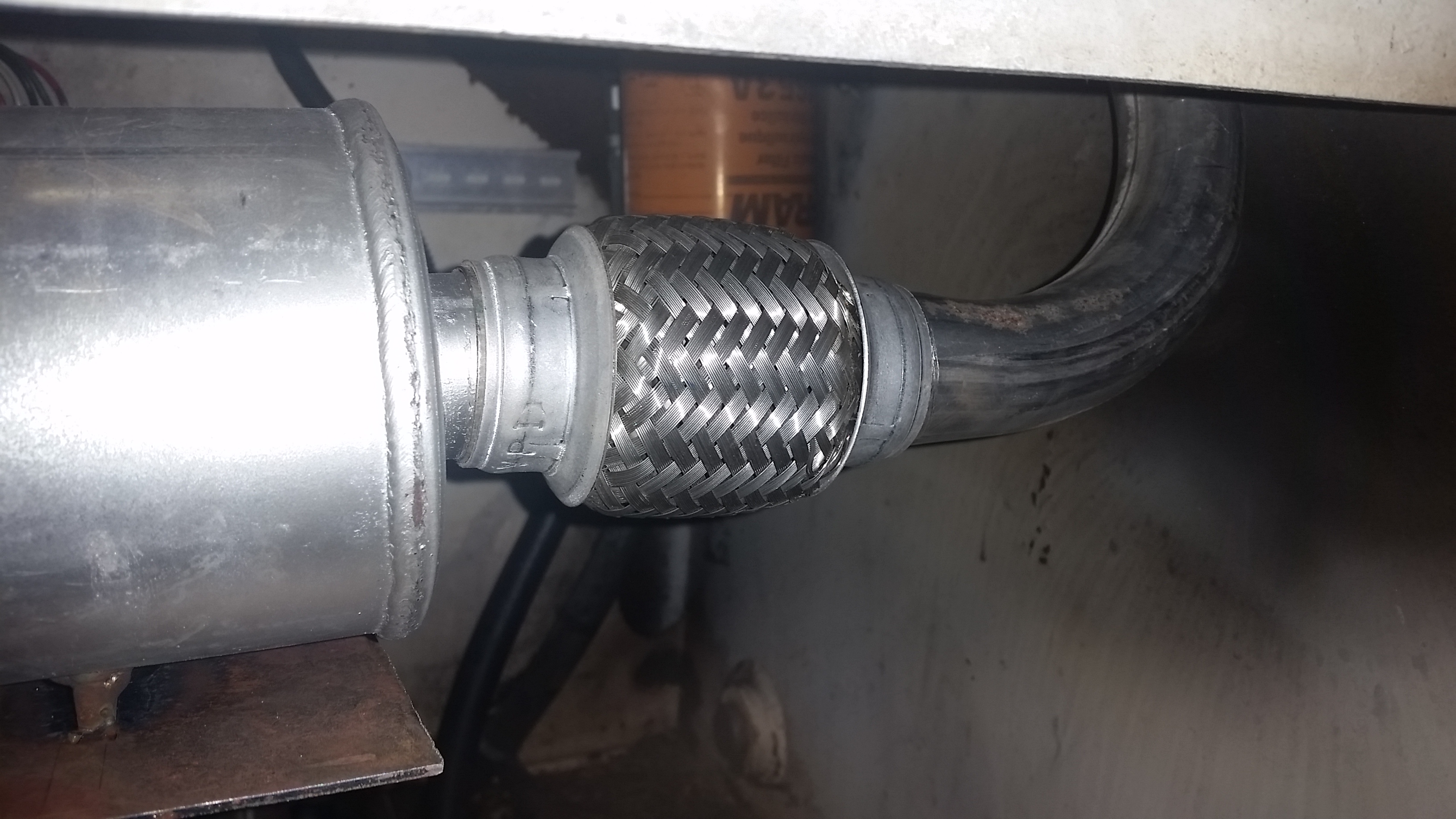
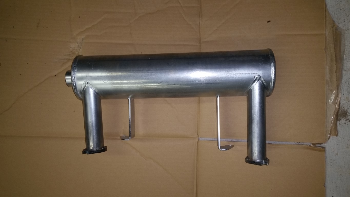
This is the exhaust (muffler) I also bought, ready for modification:
2014-09-08_07.jpg
 
OP
OP
P

peebeeaitch

Well-known member
Joined
Dec 3, 2012
Messages
115
Yay!! Love seeing repowers!! Keep the pic's coming!!
2014-09-08
During the research for which motor to buy, I quickly realized that this whole episode would cost a lot more and be a much bigger pain if I needed to drop the motor - I was therefore careful in making sure the B&S motor had a lower foot-to-crank height than the Wisconsin.
If anyone's ever tried getting accurate drawings of the Wisconsin, they'll empathise with me. I must have looked at dozens of line drawings, but nowhere do they show the distance (even inferred) from the level at which Bobcat mounted the engine to the centre of the crank. I decided I needed to measure:
2014-09-08_02.jpg

(This is the equivalent measurement I made on the B&S to confirm the measurement result and to double check the drawings - I made the same measurement on the Wisconsin).
This was all pasted into SolidWorks and voila:
2014-09-08_10.jpg

The four pads on top of the two plates represent the foot mount hole locations of the B&S. In all B&S manuals from 2010 the 35 HP Vanguard is shown, but in none of them the actual foot mount dimensions are given. I wrote to B&S to ask if they could provide the following dimensions:
2014-09-11_01.jpg

After backwards and forwardsing the customer services agent, this was the result:
2014-09-11_02.jpg

WHAT?????!!!!!!?!?!?!?! How can Briggs & Stratton, the makers of the Vanguard, not have drawings of their motor, or be prepared to release the foot mount locations, or not have a vernier caliper to run down to the warehouse and get the measurements. Absolutely incredible.
I made a tracing of the bottom of the motor, and made as many measurements as I could. I then drew this up in SolidWorks, and then had another (rare) brainwave. Looking through the B&S 2013 manual, it appears as if the 31 HP Vanguard and the 35 HP Vanguard share the same foot mount, and the foot mount drawings for the 31 HP are in the manual. So I modified my model to the 31 HP foot mount line drawings.
In the SolidWorks model shown above, one can see two stacked plates. Laser machines really don't like cutting holes < material thickness. As the hole diameter for the foot bolts is 9.5mm, the thickest material I wanted was 10mm. However, the model showed that the total packer thickness required was around 15.95mm - very close to 8mm x 2, or here in the US, 5/16" x 2. If I used 2x 5/16", it left me with a total packer error in thickness of 0.1mm, which I was prepared to ignore because of all of the other measurement inaccuracies.
This is the resulting plate:
2014-09-16_02.jpg

In the manual on the foot mount it indicates that the bolt holes in the block narrow from 3/8" at the bottom to something arbitrary at the top, so I accurately "reamed" the holes open to 3/8" using a 3/8" titanium coated Bosch drill bit and Hitachi cordless screwdriver.
I also noticed that though there are 8 mounting holes, the groups of two are so closely spaced that it is impossible to get two nuts onto the two adjacent bolts, so I decided to only use 4 bolts.
Here is the plate aligned with the motor:
2014-09-15_07.jpg

In the picture one can see a wave in the top leg of the plate. This is a scrap plate that shifted when the plate moved on the laser table. The holes are accurate though because the laser machine first cuts the holes, then the outline. The two plates I intended to use for the job didn't have this defect.
I dry fitted the motor and made sure that things at least appeared correct, without the plates welded in place. I then welded them and this is the result:
2014-09-16_01.jpg
 
OP
OP
P

peebeeaitch

Well-known member
Joined
Dec 3, 2012
Messages
115
2014-09-08
During the research for which motor to buy, I quickly realized that this whole episode would cost a lot more and be a much bigger pain if I needed to drop the motor - I was therefore careful in making sure the B&S motor had a lower foot-to-crank height than the Wisconsin.
If anyone's ever tried getting accurate drawings of the Wisconsin, they'll empathise with me. I must have looked at dozens of line drawings, but nowhere do they show the distance (even inferred) from the level at which Bobcat mounted the engine to the centre of the crank. I decided I needed to measure:

(This is the equivalent measurement I made on the B&S to confirm the measurement result and to double check the drawings - I made the same measurement on the Wisconsin).
This was all pasted into SolidWorks and voila:

The four pads on top of the two plates represent the foot mount hole locations of the B&S. In all B&S manuals from 2010 the 35 HP Vanguard is shown, but in none of them the actual foot mount dimensions are given. I wrote to B&S to ask if they could provide the following dimensions:

After backwards and forwardsing the customer services agent, this was the result:

WHAT?????!!!!!!?!?!?!?! How can Briggs & Stratton, the makers of the Vanguard, not have drawings of their motor, or be prepared to release the foot mount locations, or not have a vernier caliper to run down to the warehouse and get the measurements. Absolutely incredible.
I made a tracing of the bottom of the motor, and made as many measurements as I could. I then drew this up in SolidWorks, and then had another (rare) brainwave. Looking through the B&S 2013 manual, it appears as if the 31 HP Vanguard and the 35 HP Vanguard share the same foot mount, and the foot mount drawings for the 31 HP are in the manual. So I modified my model to the 31 HP foot mount line drawings.
In the SolidWorks model shown above, one can see two stacked plates. Laser machines really don't like cutting holes < material thickness. As the hole diameter for the foot bolts is 9.5mm, the thickest material I wanted was 10mm. However, the model showed that the total packer thickness required was around 15.95mm - very close to 8mm x 2, or here in the US, 5/16" x 2. If I used 2x 5/16", it left me with a total packer error in thickness of 0.1mm, which I was prepared to ignore because of all of the other measurement inaccuracies.
This is the resulting plate:

In the manual on the foot mount it indicates that the bolt holes in the block narrow from 3/8" at the bottom to something arbitrary at the top, so I accurately "reamed" the holes open to 3/8" using a 3/8" titanium coated Bosch drill bit and Hitachi cordless screwdriver.
I also noticed that though there are 8 mounting holes, the groups of two are so closely spaced that it is impossible to get two nuts onto the two adjacent bolts, so I decided to only use 4 bolts.
Here is the plate aligned with the motor:

In the picture one can see a wave in the top leg of the plate. This is a scrap plate that shifted when the plate moved on the laser table. The holes are accurate though because the laser machine first cuts the holes, then the outline. The two plates I intended to use for the job didn't have this defect.
I dry fitted the motor and made sure that things at least appeared correct, without the plates welded in place. I then welded them and this is the result:
Thanks SkidRoe,
When I buy potentially expensive tools, I usually first buy the cheapest POS I can find. If I find I need the tool and it breaks, I go out and buy the best quality replacement I can find.
With the Bobcat this has not worked out (things are pretty expensive when one is talking mobile machinery), so I need to make this little machine work.
As it is, the impetus for the re-engine comes from the Queen Bee wanting me to do all sorts of things around the house that are going to require my sweat, or a working Bobcat. Guess what I'm choosing?
 

Tazza

Moderator
Staff member
Joined
Dec 7, 2004
Messages
16,836
Thanks SkidRoe,
When I buy potentially expensive tools, I usually first buy the cheapest POS I can find. If I find I need the tool and it breaks, I go out and buy the best quality replacement I can find.
With the Bobcat this has not worked out (things are pretty expensive when one is talking mobile machinery), so I need to make this little machine work.
As it is, the impetus for the re-engine comes from the Queen Bee wanting me to do all sorts of things around the house that are going to require my sweat, or a working Bobcat. Guess what I'm choosing?
That is pretty poor service os B&S, they will have tech drawings, they just don't feel like sharing them. They are mounting details, nothing that is needed to be kept secret.....
Looking good so far, wish i had access to a laser cutter :)
 
OP
OP
P

peebeeaitch

Well-known member
Joined
Dec 3, 2012
Messages
115
That is pretty poor service os B&S, they will have tech drawings, they just don't feel like sharing them. They are mounting details, nothing that is needed to be kept secret.....
Looking good so far, wish i had access to a laser cutter :)
Thanks Tazza,
The thing about laser cutters is that they are really accessible. It is really easy to find one that does job shop stuff and it's amazing what they can do, even if it takes a week for delivery.
If anyone needs tips please PM me, I've been using them for 14 years (and installed 2) and I've saved 100's of hours using their abilities. They really are a commodity service now, sort of like a battery testing place.
peebeeaitch
 

Tazza

Moderator
Staff member
Joined
Dec 7, 2004
Messages
16,836
Thanks Tazza,
The thing about laser cutters is that they are really accessible. It is really easy to find one that does job shop stuff and it's amazing what they can do, even if it takes a week for delivery.
If anyone needs tips please PM me, I've been using them for 14 years (and installed 2) and I've saved 100's of hours using their abilities. They really are a commodity service now, sort of like a battery testing place.
peebeeaitch
That and i assume their cuts are precise and neat.
Just how thick can they cut? i know plasma can cut pretty thick and still be a very tidy cut, but you do get that line on the back of the cut steel, easy to knock off.
 
OP
OP
P

peebeeaitch

Well-known member
Joined
Dec 3, 2012
Messages
115
That and i assume their cuts are precise and neat.
Just how thick can they cut? i know plasma can cut pretty thick and still be a very tidy cut, but you do get that line on the back of the cut steel, easy to knock off.
The cuts are incredible - not to start a firestorm here, but even HD Plasma does not even come close.
The thickest cut is really 25mm - I have heard of slightly thicker cuts, but you won't easily find a supplier that would be prepared (or able) to do this. Please note that this is mild steel. In aluminium the cut is a lot thinner and stainless even less.
Here is the cut on a 20mm piece of mild steel:
2014-09-18_01.jpg

(At the top of the picture is the back - notice how little dross there is)
2014-09-18_02.jpg

(Bottom of picture is top of steel)
2014-09-18_03.jpg

And the above picture is the width that was cut without any distortion.
The minimum round (not ugly, or oblong, or "looks like a hole but isn't") hole diameter on a Trumpf machine is around 0.6x material thickness (so 12mm on a 20mm plate). Most job shops won't cut this though as the cost for this type of cutting is very high. Instead they'll mark the steel with an etched cross (which is pretty pathetic actually) and will cut any hole that is material thickness or more in diameter.
A serious word of caution to anyone that wants something laser cut: do not expect to get sharp corners. The reason is that the machine is moving full speed along, say, the X axis. Now the program calls for a perpendicular cut along the Y. When the machine gets to the corner, it needs to stop moving in X and simultaneously accelerate in Y. The result is that the laser beam dwells at the corner for a split second, and that split second is enough to cause a horrible burn mark there. Apparently dermatological lasers output around 1W of laser energy, an industrial laser is 3-7kW so you get an idea of the power of the things. The result is that most software makes a small radius at a sharp corner that is dependent on material thickness:
2014-09-18_04.jpg

(This was a piece of scrap hence the skeleton cut at the top right, but the auto radius can be seen on the inside corner).
I think I have quite a comprehensive knowledge of these machines so if anyone wants some help with designs, give me a PM and I'll see if I can help out.
 

SkidRoe

Well-known member
Joined
Dec 10, 2009
Messages
1,885
The cuts are incredible - not to start a firestorm here, but even HD Plasma does not even come close.
The thickest cut is really 25mm - I have heard of slightly thicker cuts, but you won't easily find a supplier that would be prepared (or able) to do this. Please note that this is mild steel. In aluminium the cut is a lot thinner and stainless even less.
Here is the cut on a 20mm piece of mild steel:

(At the top of the picture is the back - notice how little dross there is)

(Bottom of picture is top of steel)

And the above picture is the width that was cut without any distortion.
The minimum round (not ugly, or oblong, or "looks like a hole but isn't") hole diameter on a Trumpf machine is around 0.6x material thickness (so 12mm on a 20mm plate). Most job shops won't cut this though as the cost for this type of cutting is very high. Instead they'll mark the steel with an etched cross (which is pretty pathetic actually) and will cut any hole that is material thickness or more in diameter.
A serious word of caution to anyone that wants something laser cut: do not expect to get sharp corners. The reason is that the machine is moving full speed along, say, the X axis. Now the program calls for a perpendicular cut along the Y. When the machine gets to the corner, it needs to stop moving in X and simultaneously accelerate in Y. The result is that the laser beam dwells at the corner for a split second, and that split second is enough to cause a horrible burn mark there. Apparently dermatological lasers output around 1W of laser energy, an industrial laser is 3-7kW so you get an idea of the power of the things. The result is that most software makes a small radius at a sharp corner that is dependent on material thickness:

(This was a piece of scrap hence the skeleton cut at the top right, but the auto radius can be seen on the inside corner).
I think I have quite a comprehensive knowledge of these machines so if anyone wants some help with designs, give me a PM and I'll see if I can help out.
Laser cutters are truly awesome. I deal with their capabilities at work on a daily basis, and it has revolutionised the way I design things.
Here is one of my home projects:
http://www.skidsteerforum.com/DesktopDefault.aspx?tabid=54&frmView=ShowPost&PostID=46363
Building this thing without a laser would have sucked!!
Cheers - SR
 
OP
OP
P

peebeeaitch

Well-known member
Joined
Dec 3, 2012
Messages
115
Laser cutters are truly awesome. I deal with their capabilities at work on a daily basis, and it has revolutionised the way I design things.
Here is one of my home projects:
http://www.skidsteerforum.com/DesktopDefault.aspx?tabid=54&frmView=ShowPost&PostID=46363
Building this thing without a laser would have sucked!!
Cheers - SR
2014-09-10
The Wisconsin engine has a taper shaft, the B&S Vanguard 35 HP 613477-2041-G1 has a 4" straight shaft.
Step 1 was to remove the Wisconsin coupling and see if I could make an adaptor for it. 2 hours later, and lots and lots of acetylene:
2014-09-10_01.jpg

Oh yes, hammers, pry bars and pullers were also employed.
2014-09-10_02.jpg

So, alternative plan 2:
2014-09-15_01.jpg

2014-09-15_02.jpg

and when slid onto the B&S shaft:
2014-09-15_03.jpg

2014-09-15_04.jpg

2014-09-15_05.jpg

The key was a little long, which a hacksaw and file corrected:
2014-09-15_06.jpg

I mated the spider to the manufactured part and slid the whole assembly in.
This was, without doubt, the most painless episode of the whole thing.
If anyone wants prints I can send them along...
 

Tazza

Moderator
Staff member
Joined
Dec 7, 2004
Messages
16,836
2014-09-10
The Wisconsin engine has a taper shaft, the B&S Vanguard 35 HP 613477-2041-G1 has a 4" straight shaft.
Step 1 was to remove the Wisconsin coupling and see if I could make an adaptor for it. 2 hours later, and lots and lots of acetylene:

Oh yes, hammers, pry bars and pullers were also employed.

So, alternative plan 2:


and when slid onto the B&S shaft:


The key was a little long, which a hacksaw and file corrected:

I mated the spider to the manufactured part and slid the whole assembly in.
This was, without doubt, the most painless episode of the whole thing.
If anyone wants prints I can send them along...
Thanks for the details on the laser cutting, i didn't know they could cut 25mm, some serious power. I would have thought they could cut the beam off for a split second for corners, but i bet the engineers know how it woeks far better than i do.
Almost no dross, unlike when i use my plasma cutter, there is always more than that.
Good progress. I assume the 2 hours with a torch and the adaptor still did not let go?
 
OP
OP
P

peebeeaitch

Well-known member
Joined
Dec 3, 2012
Messages
115
Thanks for the details on the laser cutting, i didn't know they could cut 25mm, some serious power. I would have thought they could cut the beam off for a split second for corners, but i bet the engineers know how it woeks far better than i do.
Almost no dross, unlike when i use my plasma cutter, there is always more than that.
Good progress. I assume the 2 hours with a torch and the adaptor still did not let go?
Nope, 2 hours and some choice words and it's still on the end of the motor.
The guy that manufactured the coupler wants the motor (which I will gladly donate to him for the excellent job he did on the coupler) and his statement to me was "What man put in place, man can un-put". Well, we'll see.
 
OP
OP
P

peebeeaitch

Well-known member
Joined
Dec 3, 2012
Messages
115
Nope, 2 hours and some choice words and it's still on the end of the motor.
The guy that manufactured the coupler wants the motor (which I will gladly donate to him for the excellent job he did on the coupler) and his statement to me was "What man put in place, man can un-put". Well, we'll see.
2014-09-13
The exhaust was one issue that I thought would prove vexing. The Wisconsin motor has the exhaust manifold on top of the engine, with the air cleaner remote on the left of the engine connected to it with an inlet pipe.
I specifically purchased the B&S motor with the low profile air cleaner in order that I have maximum space on top of the engine for routing the exhaust:
2014-09-19%20SEW613477-0015.jpg

vs
2014-09-19%20SEW613477-2141.jpg

(Both pictures are from SmallEngineWarehouse)
The mounting space in the engine bay is limited by the top cross-member, which limits the overall height of the replacement motor to 740mm. Wanting the exhaust as high above the air cleaner as possible to help prevent radiated heat distorting the cover, and to allow enough space to unscrew and remove the lid, I needed to use as much of this space as possible.
I put packers on top of the air cleaner, and placed the exhaust on it, increasing the packing height until the top of the exhaust was just shy of 740mm from the ground. I had previously bought a couple of 90 deg bends, all from 1.5" exhaust pipe. I cut the flanges off the exhaust and bolted them lightly to the engine. Because it is an inline V, the right cylinder exhaust port is a little back from the left exhaust port (seen from the back). I therefore cut the flange pipes a fixed distance from the exhaust box leaving a right flange and pipe which was longer than the left flange and pipe, but both pipes ending at the same point relative to the motor base.
Cutting the elbow sections carefully, I found that I could use one 90 deg bend and one 45 and get up to the exhaust. I tacked everything in place.
For the additional supports, I cut the originals off the motor and then fiddled around till I could find an available bolt. The best seemed to be the ones on the valve cover. After a lot of fiddling, tacking, grinding, cutting, welding, I managed to have something that I thought would work.
2014-09-13_02.jpg

I then removed and welded the contraption.
2014-09-13_03.jpg

Ok, so a dumb mistake on my part was not tacking some more before adding lots of heat as the pipes pulled a little and required a mate of mine to hang on the ends in order to re-bolt the system in place.
I will take a better photo over the weekend of the completed setup.
 

SkidRoe

Well-known member
Joined
Dec 10, 2009
Messages
1,885
2014-09-13
The exhaust was one issue that I thought would prove vexing. The Wisconsin motor has the exhaust manifold on top of the engine, with the air cleaner remote on the left of the engine connected to it with an inlet pipe.
I specifically purchased the B&S motor with the low profile air cleaner in order that I have maximum space on top of the engine for routing the exhaust:

vs

(Both pictures are from SmallEngineWarehouse)
The mounting space in the engine bay is limited by the top cross-member, which limits the overall height of the replacement motor to 740mm. Wanting the exhaust as high above the air cleaner as possible to help prevent radiated heat distorting the cover, and to allow enough space to unscrew and remove the lid, I needed to use as much of this space as possible.
I put packers on top of the air cleaner, and placed the exhaust on it, increasing the packing height until the top of the exhaust was just shy of 740mm from the ground. I had previously bought a couple of 90 deg bends, all from 1.5" exhaust pipe. I cut the flanges off the exhaust and bolted them lightly to the engine. Because it is an inline V, the right cylinder exhaust port is a little back from the left exhaust port (seen from the back). I therefore cut the flange pipes a fixed distance from the exhaust box leaving a right flange and pipe which was longer than the left flange and pipe, but both pipes ending at the same point relative to the motor base.
Cutting the elbow sections carefully, I found that I could use one 90 deg bend and one 45 and get up to the exhaust. I tacked everything in place.
For the additional supports, I cut the originals off the motor and then fiddled around till I could find an available bolt. The best seemed to be the ones on the valve cover. After a lot of fiddling, tacking, grinding, cutting, welding, I managed to have something that I thought would work.

I then removed and welded the contraption.

Ok, so a dumb mistake on my part was not tacking some more before adding lots of heat as the pipes pulled a little and required a mate of mine to hang on the ends in order to re-bolt the system in place.
I will take a better photo over the weekend of the completed setup.
Nice work on the drive flange, definitely the way to go rather than try to make the old one work.
Thanks for the detailed updates, keep them coming!!
Cheers - SR
 
OP
OP
P

peebeeaitch

Well-known member
Joined
Dec 3, 2012
Messages
115
Any updates?
My apologies list, I was out of town for a number of weeks and forgot to post the update.
21 September 2014
Here is the motor pushed into the engine "bay".
2014-09-21_01.jpg

The aligning of the u-joint with the pumps was a real pain. For some reason, the Wisconsin just slides right in and the u-joint sort of "auto-aligns" - at least the two times I've done it. This motor just would not slide in. I assume that I have a miniscule height difference between the motor and pump centerlines. Whatever the case, I needed to loosen the spider from the front part of the u, slide it on, move the motor in place, and then tighten the 4 Allen Caps to tie the front and back sections of the u together.
2014-09-21_02.jpg

The motor I purchased did not come with any remote cables, so I bought two el-cheapos off eBay/Amazon. I also bought the Bobcat original cable holder clips (they're sitting under the two bolts on the top of the picture - something like $2.96 each). A note to our Imperial friends: this machine is truly made in Japan and is metric, hence all wrenches/spanners are metric and the holes and bolts mentioned above are M5.
Here is a video of the first run: http://www.thesouthpole.co.za/bobcat/BloodSweatAndTears/20140916_155424.mp4
One of the things I was really concerned about was the cowling at the back of the motor. My little machine came with a cowling that surrounded the Wisconsin and essentially blocked off all air above the flywheel/fan from being sucked into the fan.
2013-02-23_01.jpg

In the picture above, the engine cowling on the Wisconsin is visible, along with the mating cowling on the engine door (see the black plate in the top right corner). This cowling arrangement forces the fan to draw air through the louvres in the engine door, over the oil cooler, through the fan, over the piston heads and then out through the grating on top of the engine bay - a U shaped air flow. I was not too worried about my motor heating up, rather that the air flow over the oil cooler would not be sufficient.
2014-09-21_03.jpg

Above is the distance that the cooling fan on the B&S ended up from the oil cooler. I'm not going to redo the cowling yet, I'm going to monitor the oil temperature and see if there is something I need to do about it later. I may just make a cowling that attaches to the motor and half surrounds the oil cooler if there is a problem. Anyway, with the temperatures in Illinois at the moment I'm more worried about having to thaw the oil.
Ok, so here is the embarrassing photo:
2014-09-21_04.jpg

Looks like the left/right height on my makeshift exhaust bracket got a little mis-measured, but I'm going to leave it as is. I can, at least, take solace in the fact that I did not have a helper and so the packers/spacers and various other tricks I needed to pull to even make the holder worked to a degree and the 10mm I am out left/right is ok with me (it's not great though).
So in the intervening two months I've run the machine 0.2 hours - I know this because of this little gem: http://www.amazon.com/Briggs-Stratt...s+and+stratton+engine+hour&pebp=1416920609838
There have been three issues:
1. The weight distribution is really screwy. The Wisconsin is around 150kg and the B&S around 50kg. 100kg at the fulcrum distance has probably lost me 150-200kg on counter balance. When I have a bit of time I'm going to do the calculations and put in a decent make-up counterweight.
2. The el-cheapo throttle cable came with an el-cheapo cable clamp for the operator side. This (expletive) clamp kept on bending open, allowing the cable to slide forward, and so eliminating the full throttle position of the cable. Eventually I took the Dremel, slotted the clamp and bent the piece closest to the handle a little flat. This flat engages the cable spiral, but allows the moving section of the cable to clear, and so this problem is now gone.
3. I can't remember exactly what the specs say, but I think the WOT speed of the B&S is about 300 rpm higher than the Wisconsin. I have not yet checked the pump max RPM but to protect the pumps I'm going to have to take my RPM-o-meter and adjust down the B&S max RPM to a safe level.
The exhaust blowing into the engine bay made the engine bay a little hot. I "made" an external exhaust bend and "bracket" - if anyone wants to see it I can take a photo or two.
Let me know.
 

Tazza

Moderator
Staff member
Joined
Dec 7, 2004
Messages
16,836
My apologies list, I was out of town for a number of weeks and forgot to post the update.
21 September 2014
Here is the motor pushed into the engine "bay".

The aligning of the u-joint with the pumps was a real pain. For some reason, the Wisconsin just slides right in and the u-joint sort of "auto-aligns" - at least the two times I've done it. This motor just would not slide in. I assume that I have a miniscule height difference between the motor and pump centerlines. Whatever the case, I needed to loosen the spider from the front part of the u, slide it on, move the motor in place, and then tighten the 4 Allen Caps to tie the front and back sections of the u together.

The motor I purchased did not come with any remote cables, so I bought two el-cheapos off eBay/Amazon. I also bought the Bobcat original cable holder clips (they're sitting under the two bolts on the top of the picture - something like $2.96 each). A note to our Imperial friends: this machine is truly made in Japan and is metric, hence all wrenches/spanners are metric and the holes and bolts mentioned above are M5.
Here is a video of the first run: http://www.thesouthpole.co.za/bobcat/BloodSweatAndTears/20140916_155424.mp4
One of the things I was really concerned about was the cowling at the back of the motor. My little machine came with a cowling that surrounded the Wisconsin and essentially blocked off all air above the flywheel/fan from being sucked into the fan.

In the picture above, the engine cowling on the Wisconsin is visible, along with the mating cowling on the engine door (see the black plate in the top right corner). This cowling arrangement forces the fan to draw air through the louvres in the engine door, over the oil cooler, through the fan, over the piston heads and then out through the grating on top of the engine bay - a U shaped air flow. I was not too worried about my motor heating up, rather that the air flow over the oil cooler would not be sufficient.

Above is the distance that the cooling fan on the B&S ended up from the oil cooler. I'm not going to redo the cowling yet, I'm going to monitor the oil temperature and see if there is something I need to do about it later. I may just make a cowling that attaches to the motor and half surrounds the oil cooler if there is a problem. Anyway, with the temperatures in Illinois at the moment I'm more worried about having to thaw the oil.
Ok, so here is the embarrassing photo:

Looks like the left/right height on my makeshift exhaust bracket got a little mis-measured, but I'm going to leave it as is. I can, at least, take solace in the fact that I did not have a helper and so the packers/spacers and various other tricks I needed to pull to even make the holder worked to a degree and the 10mm I am out left/right is ok with me (it's not great though).
So in the intervening two months I've run the machine 0.2 hours - I know this because of this little gem: http://www.amazon.com/Briggs-Stratton-Maintenance-Minder-5081K/dp/B0012W3V4C/ref=sr_1_1?ie=UTF8&qid=1416920548&sr=8-1&keywords=briggs+and+stratton+engine+hour&pebp=1416920609838
There have been three issues:
1. The weight distribution is really screwy. The Wisconsin is around 150kg and the B&S around 50kg. 100kg at the fulcrum distance has probably lost me 150-200kg on counter balance. When I have a bit of time I'm going to do the calculations and put in a decent make-up counterweight.
2. The el-cheapo throttle cable came with an el-cheapo cable clamp for the operator side. This (expletive) clamp kept on bending open, allowing the cable to slide forward, and so eliminating the full throttle position of the cable. Eventually I took the Dremel, slotted the clamp and bent the piece closest to the handle a little flat. This flat engages the cable spiral, but allows the moving section of the cable to clear, and so this problem is now gone.
3. I can't remember exactly what the specs say, but I think the WOT speed of the B&S is about 300 rpm higher than the Wisconsin. I have not yet checked the pump max RPM but to protect the pumps I'm going to have to take my RPM-o-meter and adjust down the B&S max RPM to a safe level.
The exhaust blowing into the engine bay made the engine bay a little hot. I "made" an external exhaust bend and "bracket" - if anyone wants to see it I can take a photo or two.
Let me know.
Great update!
Yeah, i can see the weight difference being a problem, at least that is an easy one to fix when tilme allows.
Thanks for all the details, i'm sure someone will find it very helpful
 

discountufoparts

Well-known member
Joined
Sep 7, 2011
Messages
111
Great update!
Yeah, i can see the weight difference being a problem, at least that is an easy one to fix when tilme allows.
Thanks for all the details, i'm sure someone will find it very helpful
Thanks for all the great pictures and descriptions. I have been thinking about my options when the Kubota in my 630 goes bad.
 
OP
OP
P

peebeeaitch

Well-known member
Joined
Dec 3, 2012
Messages
115
Thanks for all the great pictures and descriptions. I have been thinking about my options when the Kubota in my 630 goes bad.
27 Nov 2014
Here are some more pics.
I mentioned to "Captain Bush" (the chap that manufactured the bush for me) that I was concerned about the exhaust heat radiating down and melting the air cleaner cover. He suggested that I make a plate between the exhaust silencer body and the air cleaner cover. I have seen this done on cars on the exhaust system and can understand that another plate that prevents the radiates heat from getting to the cover is good. Here it is:
2014-11-27_04.jpg

This is the coupling between the silencer and the exhaust outlet - the slight angle is due to the embarrassing mistake spoken of earlier:
2014-11-27_01.jpg

This is the attachment of the exhaust to the body (I've got some touch up spraying to do still):
2014-11-27_02.jpg

Here is the modification to the el-cheapo clamp bracket. The ringed part on the photo is actually where the bracket is bent down (look closely) and not the cable. It works well.
2014-11-27_03.jpg

Let me know if anyone wants more detail.
 
Top